Material band breaking device

A technology of breaking device and material belt, applied in the direction of contact parts manufacturing, etc., can solve the problems of equipment blockage, low production efficiency, unable to realize intelligent production, etc., and achieve the effect of preventing blockage and improving production efficiency.

Active Publication Date: 2013-03-13
KUNSHAN JIAHUA ELECTRONICS
View PDF4 Cites 15 Cited by
  • Summary
  • Abstract
  • Description
  • Claims
  • Application Information

AI Technical Summary

Benefits of technology

This patented technology helps create better machines that automate their process by cutting off strips or pieces instead of manually moving them out for further processing. It also improves productivity without blocking any materials with which it comes into contact during this work-up step.

Problems solved by technology

This patented technical problem addressed in the patents relates to improving the process of creating and installing electric connections between different types of electronics without damaging them due to their connection materials being used frequently.

Method used


Image

  • Material band breaking device
  • Material band breaking device
  • Material band breaking device

Examples


Embodiment Construction

[0017] The present invention will be described in detail below in conjunction with various embodiments shown in the drawings. However, these embodiments do not limit the present invention, and any structural, method, or functional changes made by those skilled in the art according to these embodiments are included in the protection scope of the present invention.

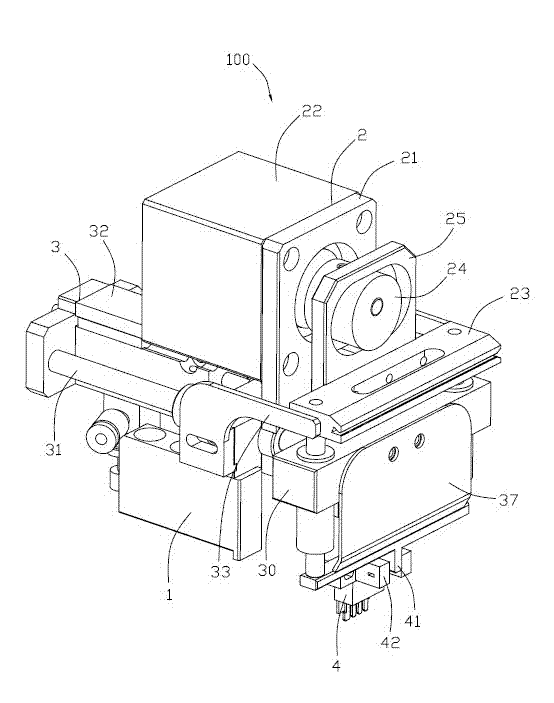
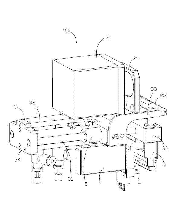
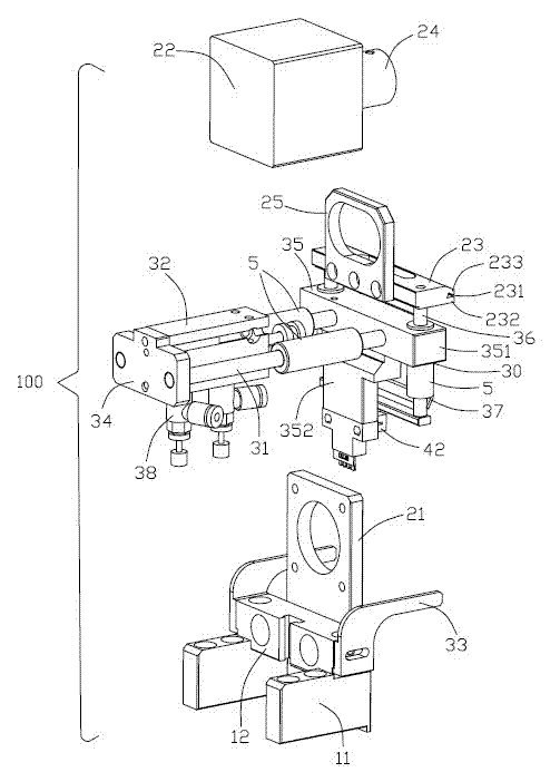
[0018] Please refer to Figure 1 to Figure 3 Shown is a preferred embodiment of the strip breaking device 100 of the present invention. The strip breaking device 100 is mainly used to break off the connecting strip (not shown) on the rear side of the formed conductive terminal (not shown), and includes a support 1 fixed on the support 1 to break the material. The breaking mechanism 2 of the belt, the ejection mechanism 3 fixed on the support 1 to push out the broken strip, and the detection mechanism 4 for detecting the working state of the breaking mechanism 2 to facilitate the control of the ejection mechanism 3 ...


PUM


Abstract

The invention provides a material band breaking device which comprises a support, a breaking mechanism fixed on the support and used for breaking a material band, and a push-out mechanism fixed on the support and used for pushing out the broken material band. The breaking mechanism comprises a first fixed board fixed on the support, a first driving mechanism fixed on the first fixed board and a material breaking board moving upward and downward under the drive of the first driving mechanism to cut off the material band. The push-out mechanism comprises first slide bars horizontally and movably positioned on the support, a connecting mechanism fixed on one ends of the first slide bars and connected to the material breaking board, a second driving mechanism which is firmly connected to the other ends of the first slide bars and drives the first slide bars to move so as to drive the material breaking board to horizontally move through the connecting mechanism, and push-out boards which are fixed on the two sides of the support and extend to the two sides of the material breaking board to push out the material band when the material breaking board moves horizontally.

Description


Claims


Application Information

Patent Timeline
Owner KUNSHAN JIAHUA ELECTRONICS
Why Eureka
Try Eureka