Rotary self-lock pull head

A self-locking and slider technology, applied in the field of zippers, can solve problems such as fragility, unstable safety protection, and complex structures

Active Publication Date: 2013-03-20
FUJIAN ZIPPER SCI & TECH CO LTD
View PDF7 Cites 9 Cited by
  • Summary
  • Abstract
  • Description
  • Claims
  • Application Information

AI Technical Summary

Problems solved by technology

The slider uses a push button switch to drive a one-way locking shrapnel built into the slider to unlock through a pull wire. It has a concealed anti-theft function, but its structure is quite complicated, and it uses a fragile pull wire. Unstable security protection

Method used


Image

  • Rotary self-lock pull head
  • Rotary self-lock pull head
  • Rotary self-lock pull head

Examples


Embodiment 1

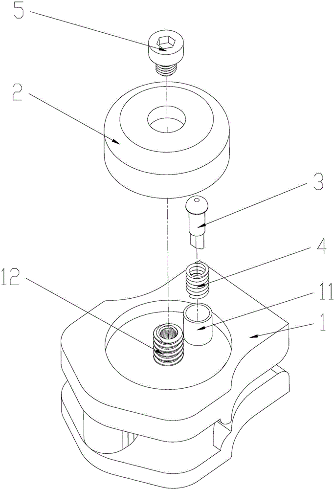
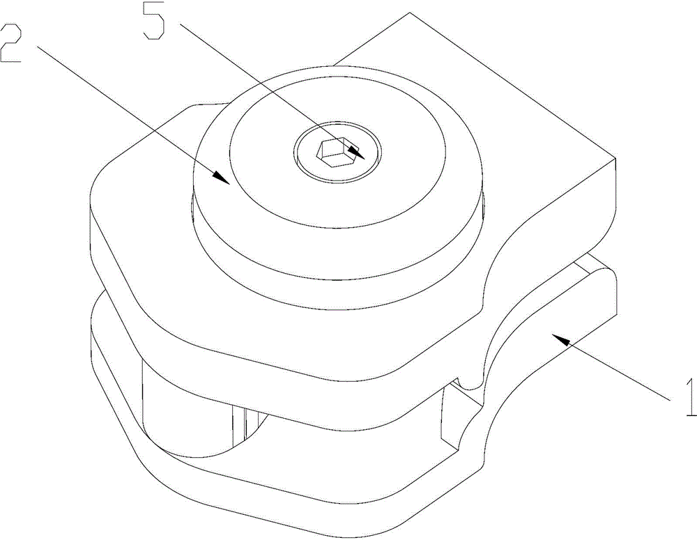
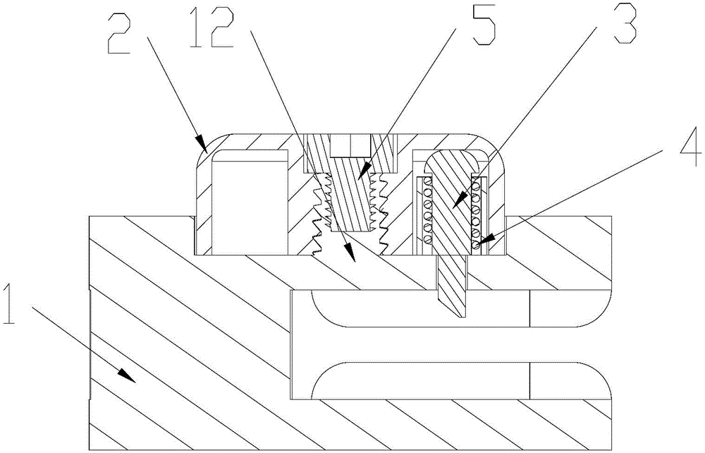
[0027] Example one, such as Figure 1-3 The fixed part shown is a bolt 5 which passes through the through hole on the cap 2 and is directly screwed on the threaded post 12. The abducted bolt head presses the step surface on the through hole of the cap 2 so that the rotating cap cannot be screwed out, so as to lock the cap 2 on the slider body 1.

Embodiment 2

[0028] Example two, such as Figure 7 As shown, the fixing member may also be a rivet 5 which passes through the through hole on the cap 2 and is directly embedded in the threaded column 12. The abducted rivet head presses the step surface on the through hole of the cap 2 so that the rotating cap cannot be screwed out, so as to lock the cap 2 on the slider body 1.

[0029] 2. Directly fixed by threaded column:

Embodiment 3

[0030] Example three, such as Figure 4-6 As shown, the present invention can also directly form a rivet head 121 that restricts the cap 2 from coming out on the top of the threaded post 12 of the upper cap 2 by screwing. The abducted rivet head buckles the step surface on the through hole of the cap 2 so that the rotating cap cannot be unscrewed to lock the cap 2 on the slider body 1.

[0031] Because the spring 4 is squeezed by the upright horse hook 3, there is always an upward force. Combined with the working principle of the thread, the rotating cap 2 rotates upwards or downwards to move the upright horse hook 3 up and down to realize unlocking and self-locking.


PUM


Abstract

The invention discloses a rotary self-lock pull head, which comprises a pull head body, a cap and a hook; the hook resists into the cap and moves upward and downward in an opening arranged on the pull head body according to a spring sleeved outside the hook; and the cap is fixedly arranged on the pull head body in a rotation manner. The action of the pull head body is realized by pulling the cap. The pull head is a novel self-lock pull head via the rotation in a threading way to realize the self-lock and the unlocking. By the utilization of the principle of working in the threading way, according to the rotation of the cap, the pull head is enabled to move upward and downward in the rotation manner, an upright hook arranged in the cap in an elasticity way is enabled to move upward and downward, and the unlocking and the self-lock are realized. The cap can be used as a pull sheet, and the number of combining parts is reduced. According to the self-lock pull head, the self-lock and unlocking of the pull head can not be realized unless removing the locking of a fixing piece, thus the self-lock pull head can be applied in clothing, a case and a tent which are self-locked or without a lock in a long term, and the self-lock pull head is provided with a certain anti-theft function.

Description

Technical field [0001] The invention relates to a zipper, in particular to a rotary self-locking and unlocking zipper pull head. Background technique [0002] Currently, the widely used self-locking zipper slider is composed of a zipper head body, a horse hook, a cap and a pull tab. You can refer to the invention patent No. CN201160563 "A zipper puller" (patent number: CN200720058045.X) published on December 10, 2008 in Chinese Patent Literature. The slider of this patent has a split structure, which is a combination of the upper and lower heads that are screwed and fixed with a nut. Although the slider can prevent others from opening the zipper easily, it cannot realize the self-locking function, which is extremely inconvenient to use. There are also zippers with anti-theft and self-locking functions, but most of them adopt an external structure. You can refer to the Chinese Invention Patent No. CN202425725U "An Anti-theft Zipper Locking Device" published on September 12, 2012...

Claims


Application Information

Patent Timeline
Patent Type & Authority Applications(China)
IPC IPC(8): A44B19/30
Inventor 张田高秀忠
Owner FUJIAN ZIPPER SCI & TECH CO LTD
Why Eureka
Try Eureka