Integrated heat dissipation structure for power electronic device and assembly method thereof

A technology of power electronic devices and heat dissipation structures, which is applied in the direction of circuit heating devices, electric solid state devices, semiconductor devices, etc., can solve the problems of complex assembly and high cost of heat dissipation structures, and achieve the effect of simple structure, less equipment investment, and less assembly parts

Pending Publication Date: 2019-03-29
常州是为电子有限公司
View PDF0 Cites 1 Cited by
  • Summary
  • Abstract
  • Description
  • Claims
  • Application Information

AI Technical Summary

Problems solved by technology

[0005] The invention provides an integrated power electronic device heat dissipation structure and its assembly method, aiming at overcoming the problem of complex assembly and high cost of the existing power electronic device heat dissipation structure

Method used


Image

  • Integrated heat dissipation structure for power electronic device and assembly method thereof
  • Integrated heat dissipation structure for power electronic device and assembly method thereof
  • Integrated heat dissipation structure for power electronic device and assembly method thereof

Examples


Embodiment Construction

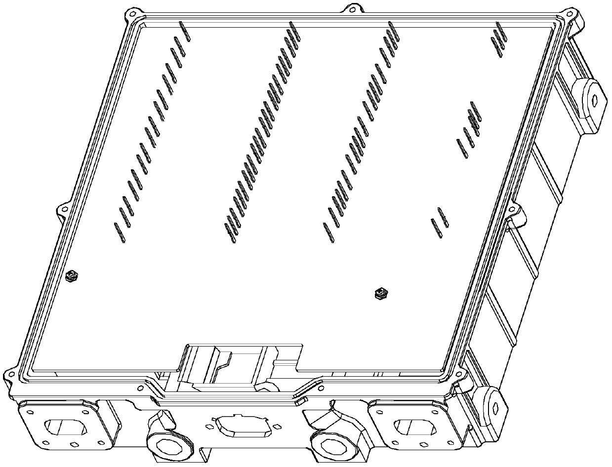
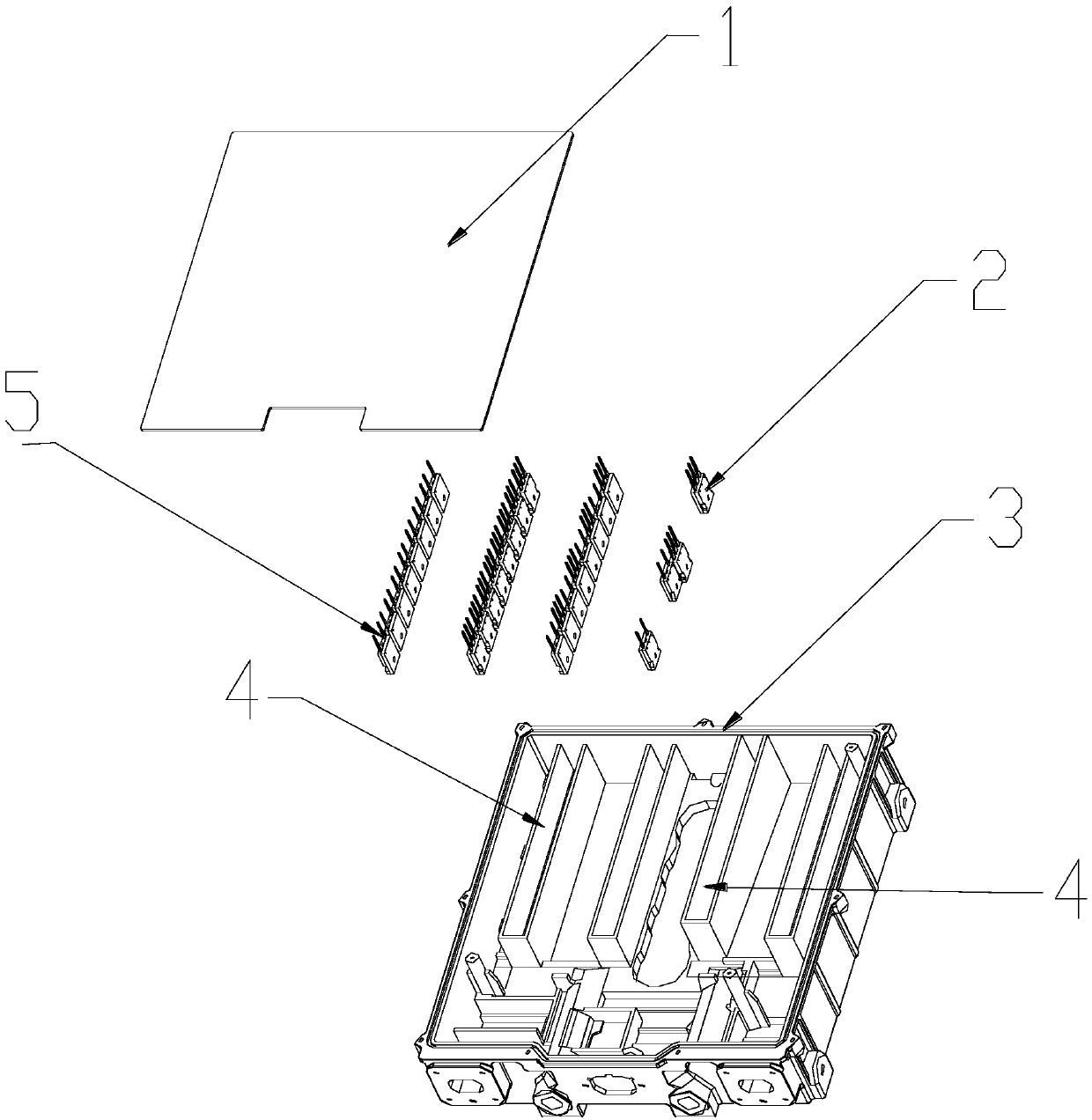
[0016] According to one or more embodiments, such as figure 1 and figure 2 As shown, the heat dissipation structure of an integrated power electronic device includes a circuit board to be assembled 1, a device MOSFET 2, a metal main shell 3, a high thermal conductivity insulating glue 4, and a device MOSFET 5.

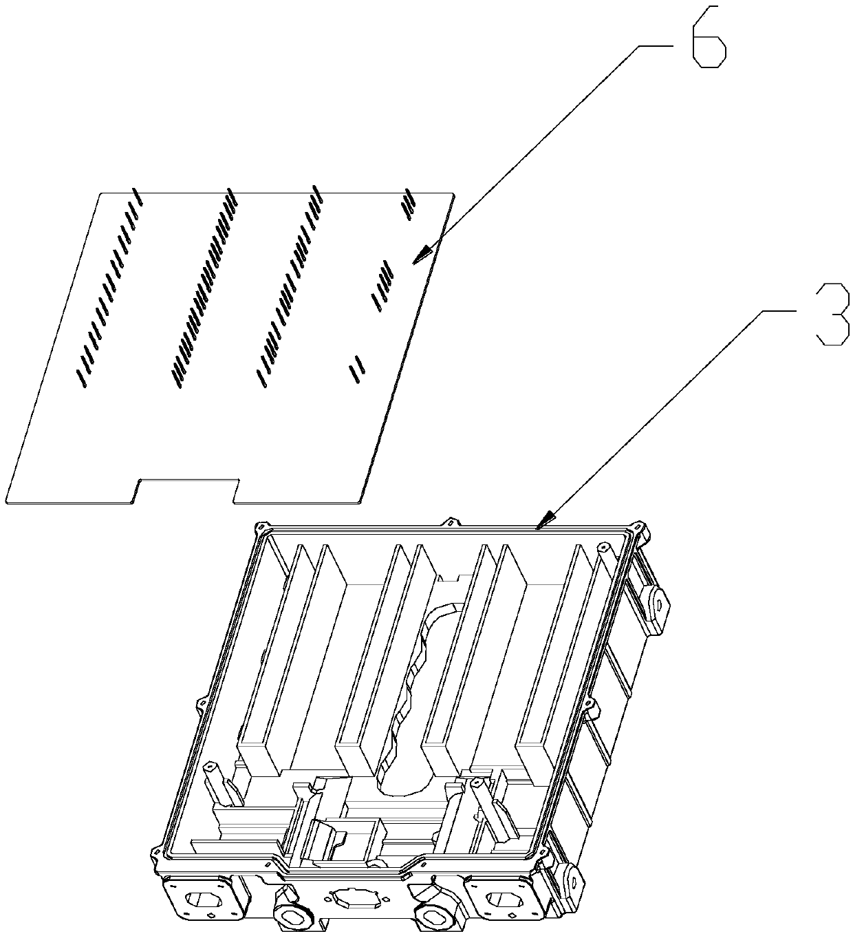
[0017] According to one or more embodiments, such as image 3 As shown, it is a schematic diagram of an assembly state of an integrated heat dissipation structure of a power electronic device. In the production process of the circuit board company, firstly, the components after welding the circuit board 1 and the device MOSFET 2 and device MOSFET 5 are shipped to the assembly factory; The coefficient insulating glue 4 is potted into the sealed cavity in the metal shell 3 after the dosage is determined. Then if image 3 As shown, the assembled circuit board assembly 6 is assembled with the metal main casing 3 . At this time, the sealed cavity of the metal main sh...


PUM


Abstract

An integrated heat dissipation structure for a power electronic device is disclosed. The heat dissipation structure includes a machine box main shell body; at least one seal cavity is fixedly mountedin the shell body; pins of the power electronic device orient upwardly to be fixedly welded to a circuit board to form a circuit board assembly; insulation paste with high heat conductivity coefficient is potted into the seal cavities; and the circuit board assembly orients downwardly with a heat dissipation surface of the body of the power electronic device, so that the body of the power electronic device penetrates into the seal cavities, and the insulation paste with the high heat conductivity coefficient seals the heat dissipation surface of the body of the power electronic device.

Description

technical field [0001] The invention belongs to the technical field of power electronic devices, and in particular relates to an integrated power electronic device heat dissipation structure and an assembly method thereof. Background technique [0002] At present, new energy vehicles, rail transit, industrial control and other fields, such as on-board chargers, DC converters, AC converters, two-in-one system integration and three-in-one system integration, etc., will use and integrate MOSFET and IGBT power electronic devices to PCB board, so as to realize the switch control of the circuit. Because MOSFET and IGBT power electronic devices have the advantages of reliability, precision, long life and high operating frequency in realizing the switch control of the circuit, they are widely used. However, the power loss of MOSFET and IGBT power electronic devices will cause serious heat generation. How to solve the temperature rise of the devices and ensure the normal operation o...

Claims


Application Information

Patent Timeline
Patent Type & Authority Applications(China)
IPC IPC(8): H01L23/29H01L23/373H01L21/56H05K1/02
CPCH01L21/56H01L23/293H01L23/3737H05K1/0209
Inventor 郭庭杨锡旺
Owner 常州是为电子有限公司
Why Eureka
Try Eureka