
Pitch changing and periodical pitch changing device of downwind wind driven generator

A technology for wind turbines and generators, which is applied in the control of wind turbines, wind turbines, and wind power generation, etc., can solve problems such as wind turbine vibration, and achieve the effects of fast pitch change, high power generation, and strong gust resistance.

Active Publication Date: 2013-03-27
张成革 +1
View PDF10 Cites 3 Cited by
  • Summary
  • Abstract
  • Description
  • Claims
  • Application Information

AI Technical Summary

Problems solved by technology

[0003] The present invention aims at the problems existing in the above-mentioned prior art, and provides a pitch change and periodic pitch change device for downwind wind power generators, which solves the problem that the entire wind power generator vibrates due to the tower shadow effect

Method used


Image

  • Pitch changing and periodical pitch changing device of downwind wind driven generator
  • Pitch changing and periodical pitch changing device of downwind wind driven generator

Examples


Embodiment 1

[0017] Such as figure 1 As shown, one end of the pitch main shaft 17 is fixedly installed on the outer frame of the wind power generator 21 through the pitch main shaft fixed installation insert 20 to prevent it from rotating, and the pitch main shaft 17 passes through the hollow generator 21 and the fan main shaft 18 passes through the pitch main shaft The bearing 16 is fixed to prevent it from shaking, and the pitch-changing main shaft 17 passes through the propeller hub 15 to form a certain included angle with the pitch-changing and periodic pitch-changing slide rails 12 . The fan main shaft 18 is hollow, and the generator 21 is also hollow, and the generator 21 is connected to the fan main shaft 18 with a coupling. The fixed installation plug-in 20 of the pitching main shaft is a spline, which is matched and installed with the pitching main shaft. The fixed installation plug-in 20 of the pitching main shaft is fixed on the outer arm of the generator so that the pitching ma...

Embodiment 2

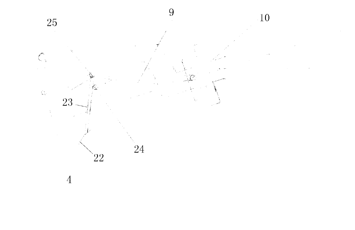
[0022] Such as figure 2 As shown, the pitch-changing action mechanism includes the main wind speed rudder and the auxiliary wind speed rudder. The length of the auxiliary wind speed rudder is smaller than that of the main wind speed rudder, and the area of ​​the auxiliary wind speed rudder is smaller than the main wind speed rudder; The other end of the main wind speed rudder stock is connected to the main wind speed rudder support arm through the main wind speed rudder shaft, and the main wind speed rudder support arm is connected to the main pitch control rod; the auxiliary wind speed rudder 22 is connected to the auxiliary wind speed rudder stock 23, and the auxiliary wind speed rudder The other end of the rod 23 is connected to the auxiliary wind speed rudder support arm through the auxiliary wind speed rudder shaft 25, and the auxiliary wind speed rudder stock 23 is connected to the pitch main connecting rod 9 through the auxiliary wind speed rudder swing arm shaft 24; th...


PUM


Abstract

The invention relates to a pitch changing and periodical pitch changing device of a downwind wind driven generator, which changes the pitch through a wind speed rudder and changes the pitch periodically. One end of a pitch changing main shaft passes through a generator and a main shaft of a fan and is fixedly arranged on an outer frame of the wind driven generator, while the other end of the pitch changing main shaft passes through a hub to form a certain included angle with a pitch changing and periodical pitch changing slide rail. The pitch changing and periodical pitch changing slide rail is provided with a fixed disc sliding in a reciprocating manner and an inclined disc. The inclined disc is movably installed on the fixed disc and rotates on the fixed disc. One end of a pitch changing connecting rod is movably connected with the inclined disc while the other end of the pitch changing connecting rod is connected with an eccentric shaft at the root of a blade. The fixed disc is connected with a reciprocating pitch changing movement mechanism through the pitch changing connecting rod. The device provided by the invention is rapid in pitch changing, strong in anti-gust capacity, and simple in structure. As the self energy of the device is not consumed to wind and pitch changing, the annual average generating capacity is high, and the period of return on investment can be shortened.

Description

technical field [0001] The present invention relates to a wind-driven generator, in particular to a pitch-changing and periodic pitch-changing device for a downwind wind-driven generator that uses a wind speed rudder to change the pitch and can periodically change the pitch. Background technique [0002] Wind power is an inexhaustible source of clean energy, and the megawatt-level has been perfected, but the structure of small and medium-sized ones is relatively complicated, the manufacturing cost is high, and the stability is poor, so it is difficult to popularize. The main reason for the high cost is that the wind-facing part and the pitch-changing part are relatively complicated, and these two parts are also prone to failure. Although there is a kind of centrifugal pitch wind turbine, although the technology is mature, it needs a relatively high speed to provide centrifugal pitch force, so it is not suitable for making it bigger, and the high speed is harmful to birds and...

Claims


Application Information

Patent Timeline
Patent Type & Authority Applications(China)
IPC IPC(8): F03D7/00
CPCY02E10/723Y02E10/72
Inventor 张成革张智蓬
Owner 张成革
Learn More