
Centrifugal Pitch Wind Turbine

A technology of wind turbines and centrifuges, applied in wind turbines, control of wind turbines, wind power generation, etc., can solve the problems of high rotational speed, damage to birds, and inability to make it bigger, so as to achieve low noise and damage to birds less, strong wind gust resistance

Active Publication Date: 2016-01-27
江苏天能海洋重工有限公司
View PDF6 Cites 0 Cited by
  • Summary
  • Abstract
  • Description
  • Claims
  • Application Information

AI Technical Summary

Problems solved by technology

Centrifugal pitching is used for stable operation and simple structure. There are currently three forms of centrifugal pitching: one is to use the whole blade as a centrifugal object, and the blade is installed in the spiral groove, and the blade rotates while sliding outwards. Its disadvantage is that the blade is too heavy as a centrifugal object, and once the blade is out of sync, it will vibrate greatly
The other is to install a centrifugal block in the propeller hub, the blades only rotate and do not slide outwards, which is safe, but since the centrifugal block is close to the center, a higher speed is required to generate centrifugal pitch force, so it cannot be made larger
There is also a way to install the centrifugal rod outside the propeller hub, the centrifugal force obtained by the centrifugal rod increases, and the wind turbine can be made larger, but the centrifugal rod will generate resistance and noise, and the speed is still faster than other pitch types with the same power The speed is high, which is harmful to birds and unfavorable to environmental protection

Method used


Image

  • Centrifugal Pitch Wind Turbine
  • Centrifugal Pitch Wind Turbine
  • Centrifugal Pitch Wind Turbine

Examples


Embodiment 1

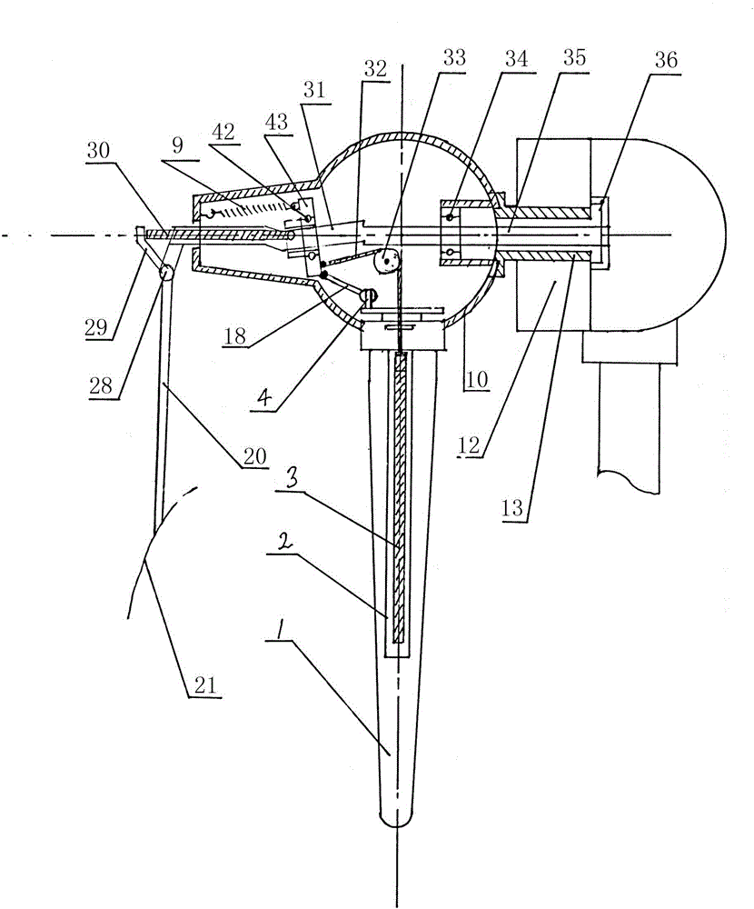
[0018] Such as figure 1 As shown, in the present embodiment, the centrifugal variable pitch wind power generator includes blade 1, generator 12, propeller hub 10, wind speed rudder 21, wind speed rudder stock 20 and wind speed rudder rocker arm 29, wind speed rudder stock 20 and wind speed rudder rocker The arms 29 are connected by the wind speed rudder shaft 28. The centrifugal body sliding sleeve 2 integrated with the blade is arranged in the blade 1. The centrifugal body sliding sleeve is hollow tubular, and a centrifugal body is installed in the centrifugal body sliding sleeve. 3. The centrifugal body 3 slides reciprocally in the centrifugal body sliding sleeve 2, and the centrifugal body is a cylinder. The centrifugal body and the paddle are connected through a wire pulley device.

[0019] The wire pulley device includes a wire rope 32, a fixed pulley 33, a swash plate 43, a pitch connecting rod 18, an eccentric shaft 4, a periodic pitch slide rail 31, a pitch tappet 30 ...

Embodiment 2

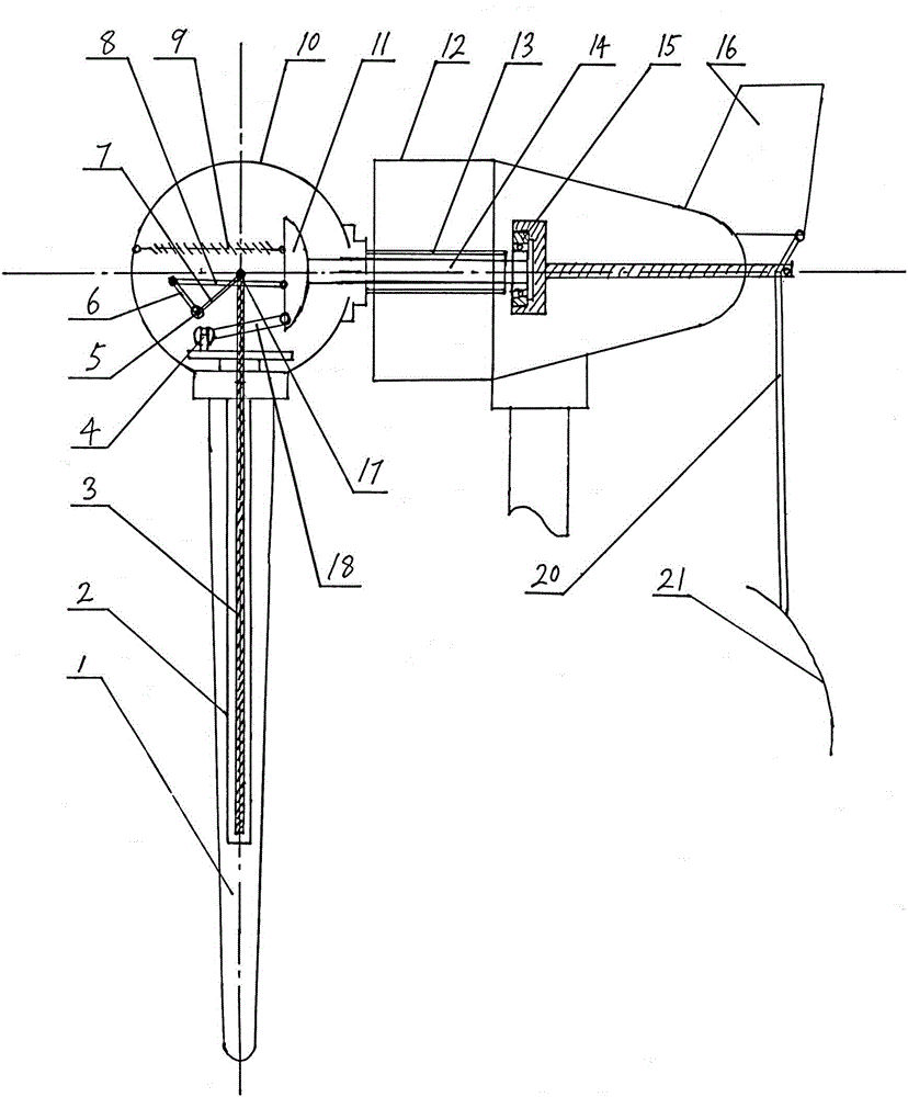
[0021] Such as figure 2 As shown, the centrifugal variable pitch wind power generator in this embodiment includes a blade 1, a generator 12, a generator hollow shaft 13 and a hub 10, and the blade 1 is provided with a centrifugal body slide integrated with the blade. Sleeve 2, the centrifugal body sliding sleeve is hollow tubular, and the centrifugal body 3 is installed in the centrifugal body sliding sleeve. The centrifugal body 3 slides back and forth in the centrifugal body sliding sleeve 2. The centrifugal body is a cylinder. The centrifugal body and the paddle The leaves are connected by a lever rocker device. The lever rocker arm device includes a centrifugal body shaft Xiao 17, a lever 7, a lever shaft 5, a rocker arm 6, a connecting rod 8, a synchronous disc 11, a pitch connecting rod 18, an eccentric shaft 4 and a return tension spring 9, The centrifugal body 3 is movably connected to one end of the lever 7 through the centrifugal body shaft Xiao 17, the rocking arm...

Embodiment 3

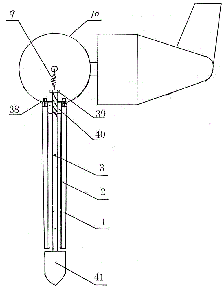
[0024] Such as image 3 As shown, the centrifugal variable pitch wind power generator in this embodiment includes a blade 1 and a hub 10, the blade 1 is provided with a centrifugal body sliding sleeve 2 integrated with the blade, and the centrifugal body sliding sleeve is a hollow tubular Yes, a centrifugal body 3 is installed in the centrifugal body sliding sleeve, and the centrifugal body 3 slides reciprocally in the centrifugal body sliding sleeve 2. The centrifugal body is a cylinder, and the centrifugal body and the paddle are connected by threads. The paddle 1 is fixed on the paddle hub 10 by screws 38, and the paddle 1 is a fixed-pitch blade. A nut 40 is arranged in the blade end, and the centrifugal body 3 is positioned at the middle part of the blade, and one end of the centrifugal body 3 is connected with the blade tip 41, and the other end of the centrifugal body is connected with the spacer 39 after passing through the nut 40, and the centrifugal body and the The ...


PUM


Abstract

The invention relates to a centrifugal variable-pitch wind driven generator. The centrifugal variable-pitch wind driven generator comprises blades and a propeller hub. Centrifugal body sliding sleeves are arranged inside the blades, are integrally connected with the blades and are in the shapes of hollow pipes. Centrifugal bodies are installed inside the centrifugal body sliding sleeves and are connected with the blades through threads, lever swinging arm devices or steel wire pulley devices. Because the centrifugal body sliding sleeves are installed inside the blades, the centrifugal bodies can conveniently slide in the blades, and the blades can be made big due to stability and safety. Being installed inside the blades, the centrifugal bodies can be arranged close to the outside as far as possible without generating noise or resistance. Because the centrifugal bodies are close to tips of the blades, the centrifugal bodies with small weights can generate large centrifugal variable-pitch force, wherein pitch angles can reach 90 degrees. The centrifugal variable-pitch wind driven generator can adapt to all kinds of wind speeds, is low in rotating speed, does less harm to birds and accords with the environmental protection concept. The centrifugal variable-pitch wind driven generator is simple in structure, low in cost, flexible in pitch changing, and strong in gust-resisting ability.

Description

technical field [0001] The invention relates to a wind-driven generator, in particular to a centrifugal variable-pitch wind-driven generator in which a centrifugal body is hidden in blades. technical background [0002] Wind power is an inexhaustible source of clean energy, and the megawatt-level ones are well established, while small and medium-sized ones still need to be perfected. Centrifugal pitching is used for stable operation and simple structure. There are currently three forms of centrifugal pitching: one is to use the whole blade as a centrifugal object, and the blade is installed in the spiral groove, and the blade rotates while sliding outwards. Its shortcoming is that the blade is too heavy as a centrifugal object, and once the blade is out of sync, it will vibrate greatly. The other is to install a centrifugal block in the propeller hub. The blades only rotate and do not slide outward, which is safe. However, since the centrifugal block is close to the center,...

Claims


Application Information

Patent Timeline
Patent Type & Authority Patents(China)
IPC IPC(8): F03D7/04F03D1/06
CPCY02E10/72
Inventor 张成革
Owner 江苏天能海洋重工有限公司
Learn More