[0017] The technical solutions in the embodiments of the present invention will be clearly and completely described below with reference to the accompanying drawings in the embodiments of the present invention.
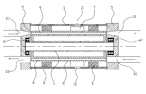
[0018] like figure 1 As shown, a gas compressor provided by an embodiment of the present invention includes a casing 1 with two ends open, one end of the casing 1 is sealed with the first end cover 2, and the other end of the casing 1 is connected with the second end cover 3. sealed connection;
[0019] The first end cover 2 and the second end cover 3 are provided with a rotating shaft 4 in the casing, the first end cover 2 is fixed with a first bearing 41 , and the second end cover 3 is fixed with a second bearing 41 . Bearing 42, the two ends of the rotating shaft 4 are respectively connected with the first bearing 41 and the second bearing 42, so as to realize the purpose of rotatingly connecting the two ends of the rotating shaft 4 with the first end cover 2 and the second end cover 3 respectively;
[0020] A rotor 5 is fixed on the rotating shaft 4, and at least one shock tube 6 is arranged on the rotor 5 along the axial direction of the rotating shaft 4. The shock tube 6 is evenly distributed on the rotor 5 along the circumferential direction. The number of tubes 6 is 1 to 100;
[0021] The first end cover 2 is provided with a high-pressure gas inlet 21 and a lowest-pressure gas outlet 22 that can communicate with the shock tube 6, and the high-pressure gas inlet 21 is used to accelerate the high-pressure gas to the speed of sound or supersonic;
[0022] The second end cover 3 is provided with a compressed high-pressure gas outlet 31 and a pre-compressed low-pressure gas inlet 32 that can communicate with the shock tube 6;
[0023] Blades 7 are fixed on the outer periphery of the rotor 5 , and a driving gas inlet 11 and a driving gas outlet 12 are provided on the casing 1 , which are directly opposite to the blades 7 .
[0024] The specific working principle of the gas compressor provided by the present invention is as follows:
[0025] (1) Incident stage: the driving gas enters the casing 1 from the gas inlet 11 of the driving casing 1, the driving gas pushes the blade 7 to rotate, and the blade 7 drives the rotor 5 to rotate together. After the rotor 5 rotates, the high-pressure gas passes through the high-pressure gas inlet 21. Accelerate and spray into the oscillating tube 6 on the rotor 5 at the speed of sound or supersonic speed, wherein the driving gas can be a small part of the high-pressure gas shunt, or it can be other gas sources, in addition, the rotation of the rotor 4 can also be Driven by motor and other equipment;
[0026] (2) Compression stage: the high-pressure gas accelerated through the high-pressure gas inlet 21 performs work on the compression of the low-pressure gas in the shock tube 6 before being compressed, because the gas injected into the shock tube 6 from the high-pressure gas inlet 21 is sonic or supersonic. , so when the high-pressure gas is injected into the shock tube 6 and encounters the pre-compressed low-pressure gas that already exists in the shock tube 6, a shock wave will be generated, and the shock wave is like an invisible piston to cut off the injected high-pressure gas and the shock wave. The low-pressure gas before being compressed in the tube 6 compresses the low-pressure gas before being compressed in the shock tube 6, so that the temperature and pressure of the low-pressure gas before being compressed in the shock tube 6 are increased, and then the compressed air is passed through the shock tube 6. The high-pressure gas outlet 31 is discharged; at the same time, the high-pressure gas injected from the high-pressure gas inlet 21 does work on the low-pressure gas before being compressed in the shock tube 6, and its own energy is consumed, so it becomes the lowest pressure gas and stays in the oscillation tube 6;
[0027] (3) Low-pressure gas injection stage before being compressed: the lowest-pressure gas left in the shock tube 6, along with the rotation of the rotor 4, will communicate with the lowest-pressure gas outlet 22 and the low-pressure gas inlet 32 before being compressed. The low-pressure gas enters the shock tube 6 through the low-pressure gas inlet 32 before being compressed, and pushes out the lowest-pressure gas in the shock tube 6, and the lowest-pressure gas is discharged through the lowest-pressure gas outlet 22. Before being compressed, the low-pressure gas remains in the shock wave. In the tube 6; with the rotation of the rotor 5, the shock tube 6 is communicated with the high-pressure gas inlet 21 and the compressed high-pressure gas outlet 31, and the low-pressure gas before being compressed in the shock tube 6 is removed from the high-pressure gas inlet 21. The incoming high pressure gas is compressed and enters the next cycle, and so on.
[0028] To sum up, unlike the prior art that uses the reciprocating motion of the piston to directly compress the gas, the gas compressor of the present invention uses high-pressure gas to compress the low-pressure gas to achieve the purpose of compressing the gas, and the compression efficiency is significantly improved. The components of the high-pressure gas and the low-pressure gas may be the same or different.
[0029] Further, two sealing plugs 8 are also arranged between the casing 1 and the rotor 5, the driving gas inlet 11 and the driving gas outlet 12 are located between the two sealing plugs 8, and the sealing plugs 8 are used to isolate the high-pressure gas, drive Gas and compressed gas to ensure the normal operation of the system.
[0030] In addition, the present invention uses the driving gas to enter the casing 1 from the driving gas inlet 11, the driving gas pushes the blades 7 to rotate, and the blades 7 drive the rotor 5 to rotate together. Therefore, the rotating shaft 4 of the present invention does not need to extend out of the casing 1 to be connected to the motor. And driven by the motor to rotate, the sealing performance of the casing 1 is significantly improved, and the leakage of the high-pressure gas in the casing 1 is greatly reduced. At the same time, because the rotating shaft 4 of the present invention does not need to extend out of the casing 1 to be connected with the motor, the volume of the entire gas wave refrigerator is reduced, and the transportation, installation and operation are convenient.
[0031] The above are the preferred embodiments of the present invention. It should be pointed out that for those skilled in the art, without departing from the principles of the present invention, several improvements and modifications can also be made, and these improvements and modifications may also be regarded as It is the protection scope of the present invention.