Supercharge Your Innovation With Domain-Expert AI Agents!

MEMS bistable optical switch and method of use thereof

一种光学开关、双稳态的技术,应用在MEMS光学开关领域,能够解决镜尺寸深度小、制造成本高等问题

Inactive Publication Date: 2016-06-22
AGILTRON
View PDF7 Cites 0 Cited by
  • Summary
  • Abstract
  • Description
  • Claims
  • Application Information

AI Technical Summary

Problems solved by technology

However, those devices use in-plane excitation for vertically etched mirrors, resulting in higher manufacturing costs and smaller mirror size depths

Method used


Image

  • MEMS bistable optical switch and method of use thereof
  • MEMS bistable optical switch and method of use thereof
  • MEMS bistable optical switch and method of use thereof

Examples


Embodiment Construction

[0015] The following Detailed Description describes the current best contemplated mode of carrying out the teachings. The description should not be read in a limiting sense, but is presented merely as an illustration of the general principles of these teachings, since the scope of these teachings is best defined by the appended claims.

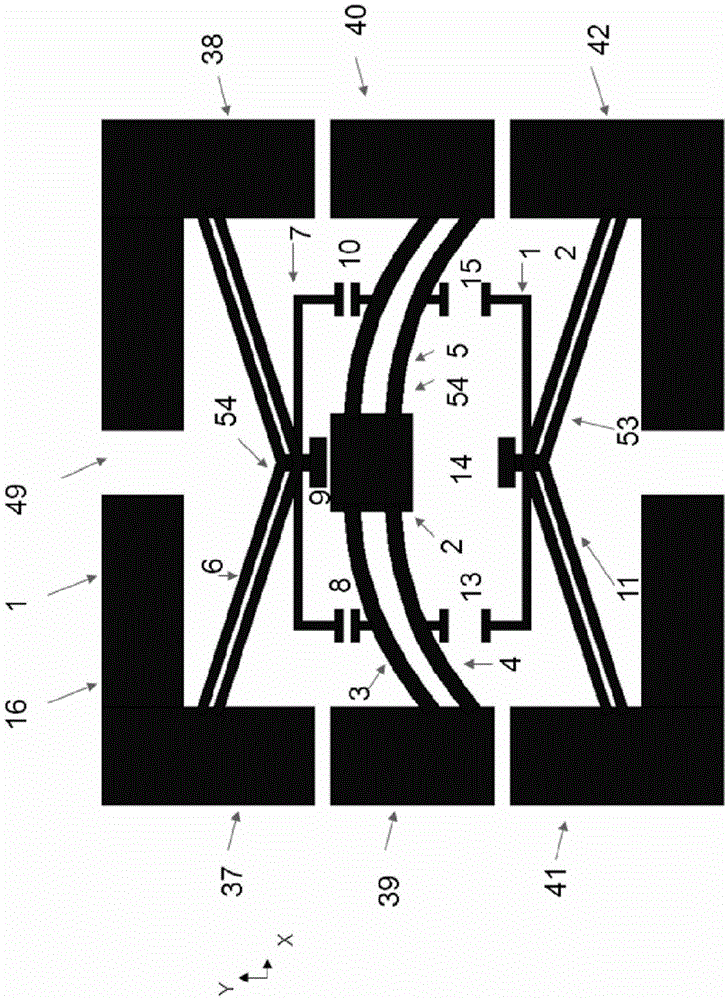
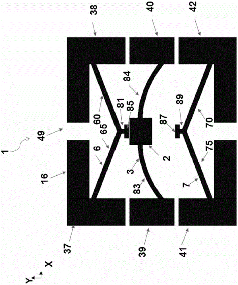
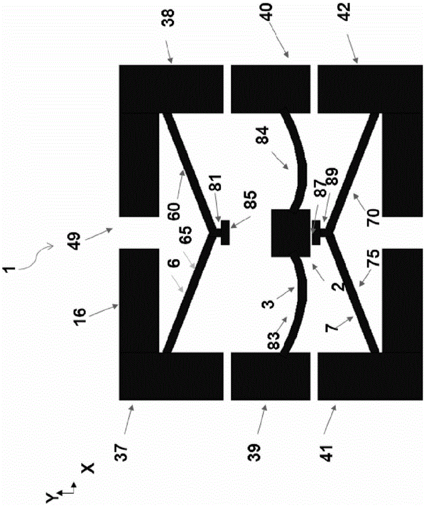
[0016] In one embodiment, the present teachings overcome the above problems by providing an optical switch that uses one or more elements of a microelectromechanical systems (MEMS) device aligned with one or more fiber optic collimators to direct light beams from one or more input ports to one or more output ports. In that embodiment, the MEMS chip has an in-plane optical reflective component (such as but not limited to a mirror) and two electrothermal actuator components suspended on a self-latching bistable mechanism. The actuator drives the bistable mechanism from its first stable position to its second stable position and from its second ...


PUM


Abstract

An optical switch comprising: a bistable component; a reflective component operatively connected to the bistable component; a first electrothermal bending beam actuator; a first contact component operatively connected to the first electrothermal bending beam a beam actuator assembly, a first electrothermal bending beam actuator assembly and a first contact assembly positioned to enable advancement of the bistable assembly and the reflective assembly from a first stable configuration to a second stable configuration; a second electrothermal bending beam actuator assembly; and a second contact assembly operatively connected to a second electrothermal bending beam actuator assembly, the second electrothermal bending beam actuator assembly and the second contact assembly being positioned to enable the bistable assembly and the reflective assembly to move from a second stable configuration Advance to first stable configuration.

Description

technical field [0001] These technical teachings generally relate to MEMS optical switches. Background technique [0002] An optical switch is a device that transmits optical signals along selected optical fibers of an optical network. These switches form the fundamental building blocks of modern optical networks. Prior art optical switches are mainly based on mechanisms that perform mechanical movements, change the waveguide coupling ratio and perform polarization rotation. Optical switches based on mechanical relays have large dimensions. In MEMS technology there has been a significant focus on small size optical switches. Among them, the device based on MEMS electrostatic rotating mirror is the most common method. However, these devices require high electric fields to generate sufficient actuation force, which results in costly hermetic packaging. Additionally, these devices are non-latching and the switch state is lost when external power is lost. Bistable mechanis...

Claims


Application Information

Patent Timeline
Patent Type & Authority Patents(China)
IPC IPC(8): G02B26/08B81B3/00
CPCG02B26/0866Y10S359/90
Inventor 尹露中钟桂雄寿援新艾米特·戈萨颜军赵京
Owner AGILTRON
Features
  • R&D
  • Intellectual Property
  • Life Sciences
  • Materials
  • Tech Scout
  • Unparalleled Data Quality
  • Higher Quality Content
  • 60% Fewer Hallucinations
Learn More