
Method used for providing display in motor vehicle according to visual direction of vehicle driver

A driver, motor vehicle technology, applied in the field of providing a display in a motor vehicle according to the viewing direction of the driver of the vehicle

Active Publication Date: 2013-03-27
AUDI AG
View PDF7 Cites 13 Cited by
  • Summary
  • Abstract
  • Description
  • Claims
  • Application Information

AI Technical Summary

Problems solved by technology

[0005] An ever-present technical problem is that of making the driver of a vehicle notice a particular object strongly and particularly quickly

Method used


Image

  • Method used for providing display in motor vehicle according to visual direction of vehicle driver

Examples


Embodiment Construction

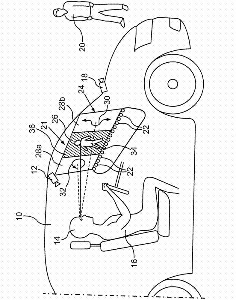
[0018] The motor vehicle marked as a whole with "10" has at least one camera 12 which is aimed at the head 14 of the driver 16 of the motor vehicle and thus can detect the direction of view of the driver 16 of the motor vehicle. A further camera 18 detects the environment outside the motor vehicle, for example pedestrians 20 . In a motor vehicle, a row of light-emitting diodes 22 is provided, wherein the light-emitting diodes are arranged, for example, in pairs of (in each case) two light-emitting diodes, in which one light-emitting diode emits red light and the other green light. Furthermore, a head-up display 21 can be provided in the motor vehicle 10 , ie a display can be made on a windshield 24 of the motor vehicle.

[0019] In the present (shown) situation, it is desirable to draw the attention of the motor vehicle driver 16 to the pedestrian 20 by means of a display. For this purpose, the viewing direction is continuously detected by means of the camera 12 and whether t...


PUM


Abstract

The present invention relates to a method used for providing display on at least one display position in a motor vehicle, through the method, physiological conditions of eyes can be well taken into account. In the method, the display is selected from at least two kinds of display types on the basis that the corresponding display position is located in a central vision field (26) of the vehicle driver or is located in peripheral vision fields (28a, 28b) of the vehicle driver. In the central vision field (26) of the vehicle driver (16), contrast between intense colors is preferredly selected, while in the peripheral vision fields (28a, 28b), the display changes over time is selected.

Description

technical field [0001] The invention relates to a method for providing a display at at least one display point in a motor vehicle. Such a display point can be a display device provided specifically for display, such as a screen or a display, or a plurality of light-emitting diodes, but it can also be a projection surface, wherein here in particular the windshield is suitable for so-called head-up Display (Head-up-Display). Background technique [0002] It is known from DE 10 2005 058 018 A1 to transmit such a head-up display in a targeted manner into the field of view of the observer when the direction of sight of the driver of the vehicle is detected. In particular, a visual aid should be provided here: elements are projected into the viewer's field of view in such a way that they coincide / correlate with the corresponding actual object. This can be achieved in that the environment sensor device acquires information about actual objects in the environment. [0003] DE 102...

Claims


Application Information

Patent Timeline
Patent Type & Authority Applications(China)
IPC IPC(8): G02B27/01B60R1/00B60R1/10
CPCH04N7/185G02B27/01G02B2027/0112B60R2300/308G02B2027/0187B60R2300/205B60R1/00B60K35/10B60K35/29B60K2360/191B60K35/235B60K35/28B60K35/00B60K2360/149
Inventor B·吉斯勒T·克尔佐B·雅各布斯
Owner AUDI AG
Learn More