
Sample based image repairing method

A repair method and image technology, applied in image enhancement, image data processing, instruments, etc., can solve the problem of not being able to intelligently generate the required information for the damaged area, not being able to restore the structure information and texture information synchronously, scratch repair and object removal Not bad and other problems to achieve the effect of avoiding dropping effect, ensuring precision and accuracy, and ensuring accuracy

Active Publication Date: 2015-07-01
GRADUATE SCHOOL OF THE CHINESE ACAD OF SCI GSCAS
View PDF3 Cites 0 Cited by
  • Summary
  • Abstract
  • Description
  • Claims
  • Application Information

AI Technical Summary

Problems solved by technology

However, in the existing image restoration process, neither of the above two types of methods can achieve synchronous restoration of the structure information and texture information in the image defect area.
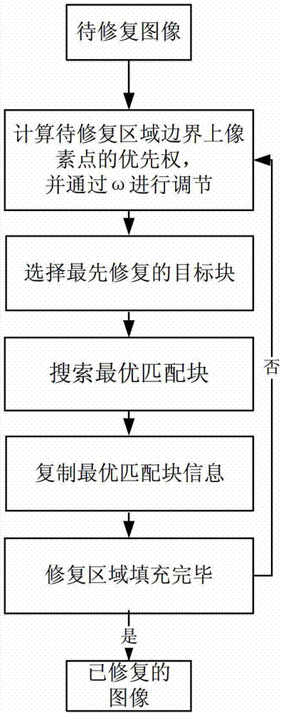
[0003] In the prior art, the sample-based image repair method completes the filling of the area to be repaired by searching for the optimal matching block of the target to be repaired in the known area. Repair the block to be repaired with the highest priority on the boundary of the area, then exhaustively search for the optimal matching block in the sample area, and finally copy the pixel value of the corresponding position of the optimal matching block to the corresponding position of the block to be repaired, because this method considers The unity of structure repair and texture repair and the rationality of repair model construction make this method obtain very good results in scratch repair and object removal, but there is a common problem in the above method, that is, it cannot intelligently generate Information Required for Damaged Areas
In other words, when the information required for the damaged area cannot be found in the known information of the image, the damaged area cannot be repaired satisfactorily.

Method used


Image

  • Sample based image repairing method
  • Sample based image repairing method
  • Sample based image repairing method

Examples


Embodiment Construction

[0032] The present invention will be described in detail below in conjunction with the accompanying drawings and embodiments.

[0033] Object removal is a typical application in the technical field of image restoration, and its task is to restore the lost image information in the specified area of ​​the image as naturally as possible. The present invention uses object removal as an example to illustrate the specific process of the image repair method. Object removal is aimed at The information defect area in the image is filled with the structure or texture information of other known areas in the image, so that the repaired image is natural and real, which meets the psychological requirements of human vision.

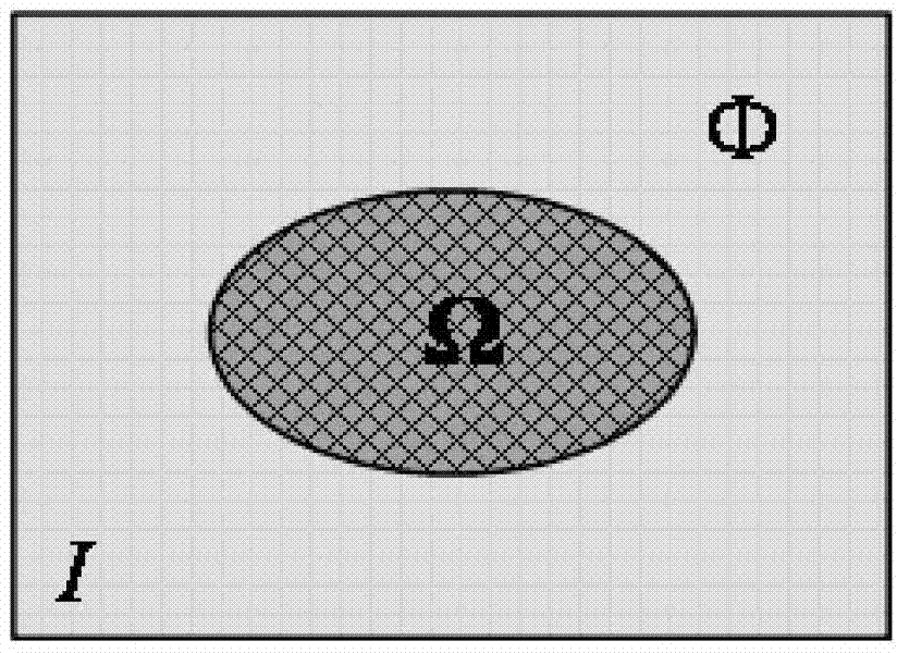
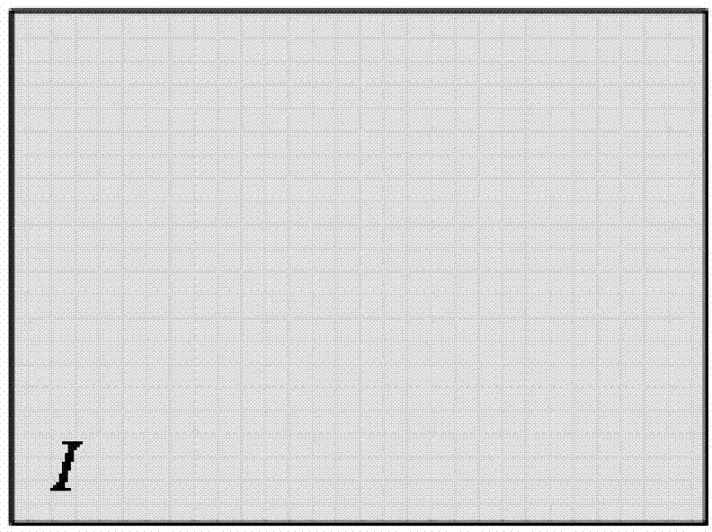
[0034] Such as figure 1 As shown, I is the image to be repaired, Ω is the specified defect area (area to be repaired), and Φ is the area with intact information in the image. Such as figure 2 As shown, from the point of view of target removal, the goal of image resto...


PUM


Abstract

The invention relates to a sample based image repairing method. The sample based image repairing method includes steps of 1), calculating priority of any one pixel point p on a boundary of an area to be repaired; 2), determining a target block to be repaired firstly according to the calculated priority of the pixel point p in the step 1); 3) searching all matched blocks in the known area, and finding the optimally matched block of the target blocks to be repaired; 4) extracting pixel value of the optimally matched block, calculating confidence coefficient value of the central pixel point of the optimally matched block; 5) copying the pixel value corresponding to the optimally matched block to the corresponding position of the target block to be repaired, updating the confidence coefficient of the point p into confidence coefficient value of the central pixel point of the optimally matched block and forming a new area to be repaired; 6) executing the steps 1) to 5) until the area to be repaired is completely filled. The sample based image repairing method can be widely applied to image repairing process.

Description

technical field [0001] The invention relates to an image repair and texture synthesis method, in particular to a sample-based image repair method suitable for repairing defective images. Background technique [0002] With the continuous progress and development of science and technology, the popularization of computer networks and the increase of people's demand for digital image information, image restoration technology has attracted more and more attention. It has been widely used in problems such as video errors, so the study of image restoration methods has great theoretical and practical value. The image inpainting method mainly combines the information around the area to be repaired in the degraded image to restore the unknown image information of the area to be repaired, so as to meet the visual psychological requirements of people. The restorative laws of visual psychology are mainly structure, similarity, structure priority and texture consistency. Image repair me...

Claims


Application Information

Patent Timeline
Patent Type & Authority Patents(China)
IPC IPC(8): G06T5/00
Inventor 吕科王静潘卫国
Owner GRADUATE SCHOOL OF THE CHINESE ACAD OF SCI GSCAS
Learn More