Card connector

A card connector, receiving space technology, applied in the direction of connection, instrument, connecting device parts, etc., can solve the problem of card connector breakage and other problems, and achieve the effect of preventing misinsertion

Active Publication Date: 2013-03-27
TYCO ELECTRONICS JAPAN GK
View PDF7 Cites 9 Cited by
  • Summary
  • Abstract
  • Description
  • Claims
  • Application Information

AI Technical Summary

Problems solved by technology

As a result, the card connect

Method used


Image

  • Card connector
  • Card connector
  • Card connector

Examples


Embodiment Construction

[0033] Embodiments of the present invention will be described below with reference to the drawings.

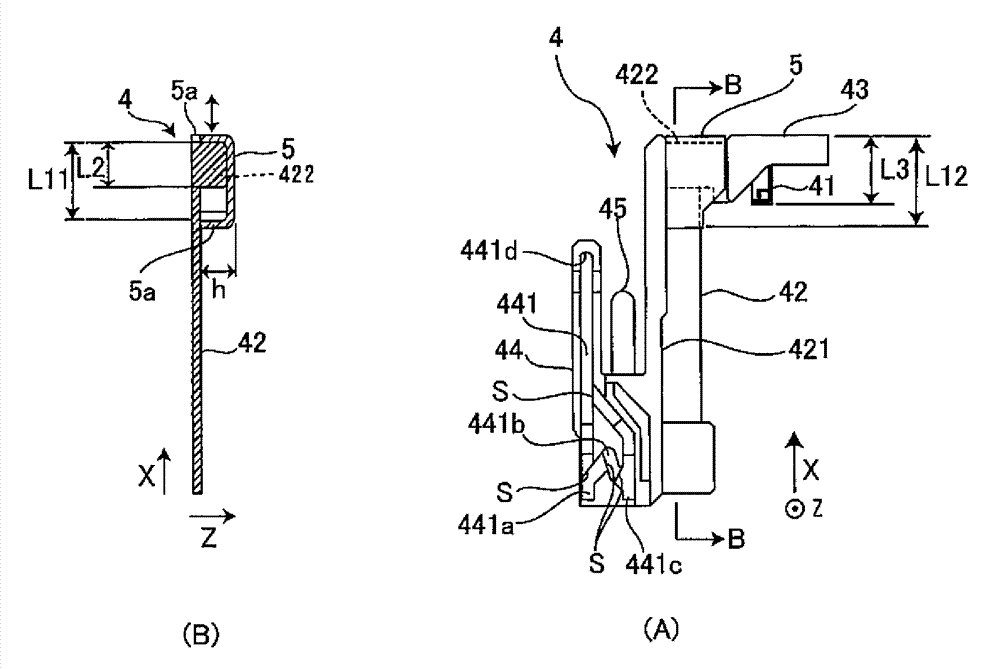
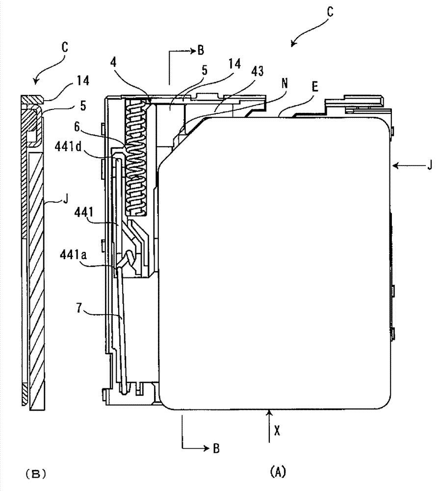
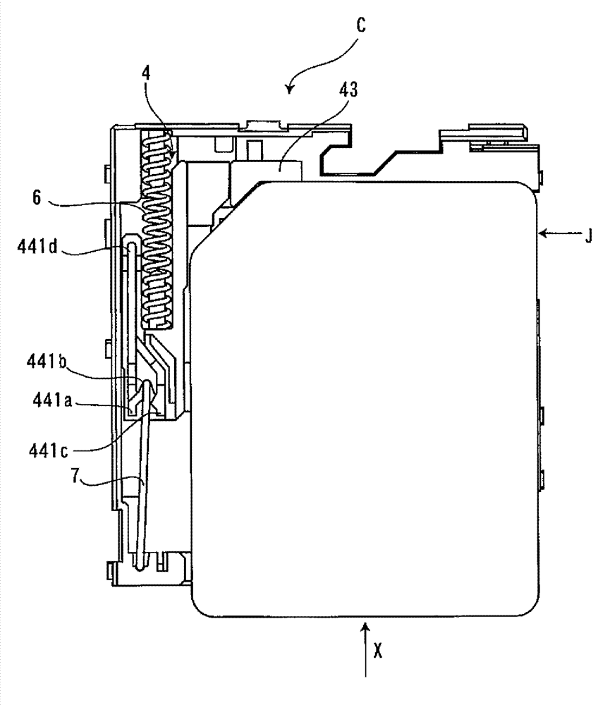
[0034] figure 1 It is a plan view of the card connector which concerns on one embodiment of this invention. exist figure 1 In , a card connector C and a card J mounted on the card connector C are shown. Here, the card J is an IC card with a built-in IC, such as a micro SIM card. exist figure 1 , card J is shown in the correct posture for insertion into card connector C. The direction in which the card J is inserted into the card connector C is referred to as "insertion direction X". The card J has a substantially rectangular plate shape, and a notch N is formed on the left and right of the front edge E in the insertion direction X. As shown in FIG. The notch N of the card J in this embodiment is at figure 1 In the correct posture shown, the card connector C is formed towards the left end. In addition, eight electrical contacts P ( P1 to P8 ) are provided in the card J....


PUM


Abstract

A card connector for receiving a card is provided. The card connector (C) includes a housing (1), a plurality of contacts (3), a slider (4) and a stopper (5). The housing (1) includes a front wall, a rear wall, and a card receiving passageway (11) formed therein. The contacts (3) are secured in the housing. The slider (4) is positioned and slidable between the front wall and the rear wall. The stopper (5) is supported by the slider (4) and includes end sections positioned adjacent to the slider (4), such that a space is provided between one of the end sections and the slider. When inserted in an improper way, the card J is prohibited by the stopper 5 to cause the slider 4 to abut the restraining wall 14, into the deepest position of the housing 1.

Description

technical field [0001] The present invention relates to card connectors. Background technique [0002] A card connector is widely known as a connector for mounting a card with built-in IC in electronic equipment typified by, for example, a mobile phone. [0003] For example, Patent Document 1 discloses a card connector having a so-called push / push type card ejection mechanism. The card connector has a cam slider in a cavity into which the card is inserted. If the inserted card is pushed again, the locking of the slider is released, and the card is pushed out by the slider. In the housing forming the cavity, protruding slide-guiding flanges are provided. In the card connector of Patent Document 1, the flange collides with the front end of the wrongly inserted card to prevent the card from being inserted. [0004] In addition, Patent Document 2 discloses a card connector having a push / push type card ejection mechanism. In this card connector, a protrusion for preventing i...

Claims


Application Information

Patent Timeline
IPC IPC(8): H01R13/64H01R12/71
CPCH01R13/62G06K7/04G06K13/0831H01R12/72H01R13/629
Inventor 辻淳也渡边树工藤祐希
Owner TYCO ELECTRONICS JAPAN GK
Why Eureka
Try Eureka