Connector

A technology of contact parts and terminals, which is applied in the direction of connection, parts of connection devices, and devices for preventing wrong connections, etc. It can solve the problems that the brake 40 cannot work smoothly, the overall weight of the joint increases, and the specificity of the terminal group is large, so as to prevent contact. , prevent mis-insertion, and improve durability

Active Publication Date: 2010-11-03
UJU ELECTRONICS +1
View PDF0 Cites 4 Cited by
  • Summary
  • Abstract
  • Description
  • Claims
  • Application Information

AI Technical Summary

Problems solved by technology

[0006] Both terminal groups have contact parts 14, 24 that apply elastic pressure to the FPC / FFC from the lower surface of the socket to the upper surface. Therefore, the more terminals in the terminal group, the greater the pressure of the contact parts 14, 24 on the brake 40. , so that the brake 40 cannot work smoothly
[0007] In addition, the two terminal groups have to bear the pressure of the brake. Therefore, in order to be effectively supported by the shell, it is often necessary to thicken or provide additional fixing parts. The overall weight of the joint will also increase, and at the same time, in order to support the pressure of the brake, the shell should also be set very thick
[0008] In addition, the above-mentioned connectors only alternately arrange terminals on one side of the FPC / FFC. Therefore, only FPC / FFC of a specific specification can be fixed, and its application range is narrow, and it also has limitations in increasing the terminal density.

Method used


Image

  • Connector
  • Connector
  • Connector

Examples


Embodiment Construction

[0026] Embodiments of the present invention will be described in detail below in conjunction with the accompanying drawings.

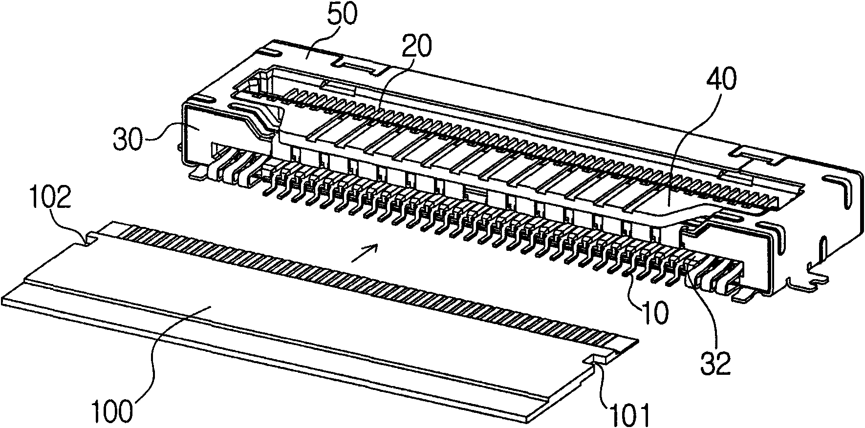
[0027] figure 2 It is a perspective view of the joint according to the present invention.

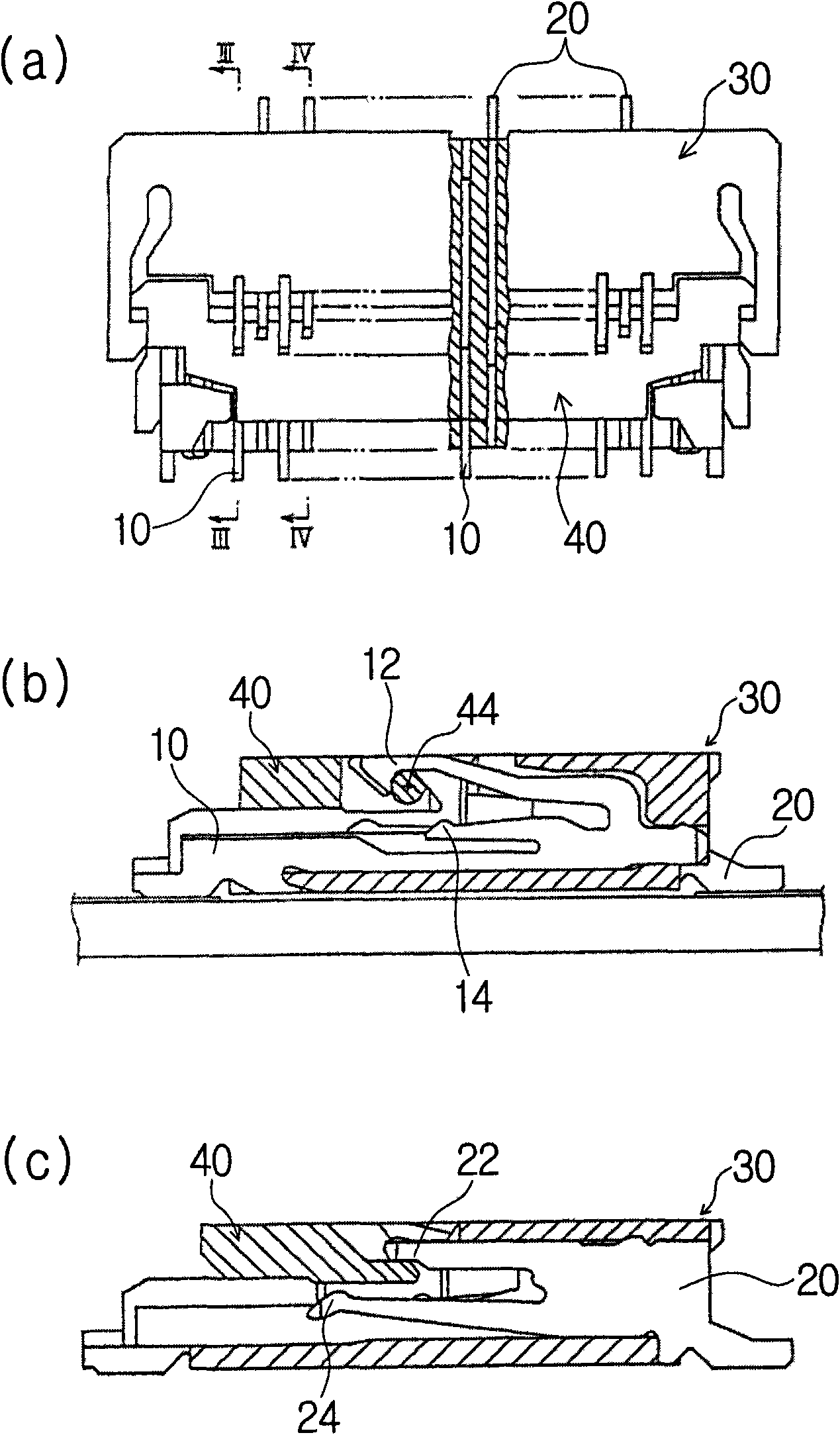
[0028] The connector of the present invention includes: a shell 30 formed with an FPC / FFC100 socket 32; the first terminal group 10 inserted / set onto the shell 30 from the direction of the socket 32 ​​of the FPC / FFC and inserted / set onto the shell 30 from the reverse direction of the socket The second terminal group 20; the brake 40 that rotates under the support of the terminals of the second terminal group 20; the outer cover 50 that wraps the shell.

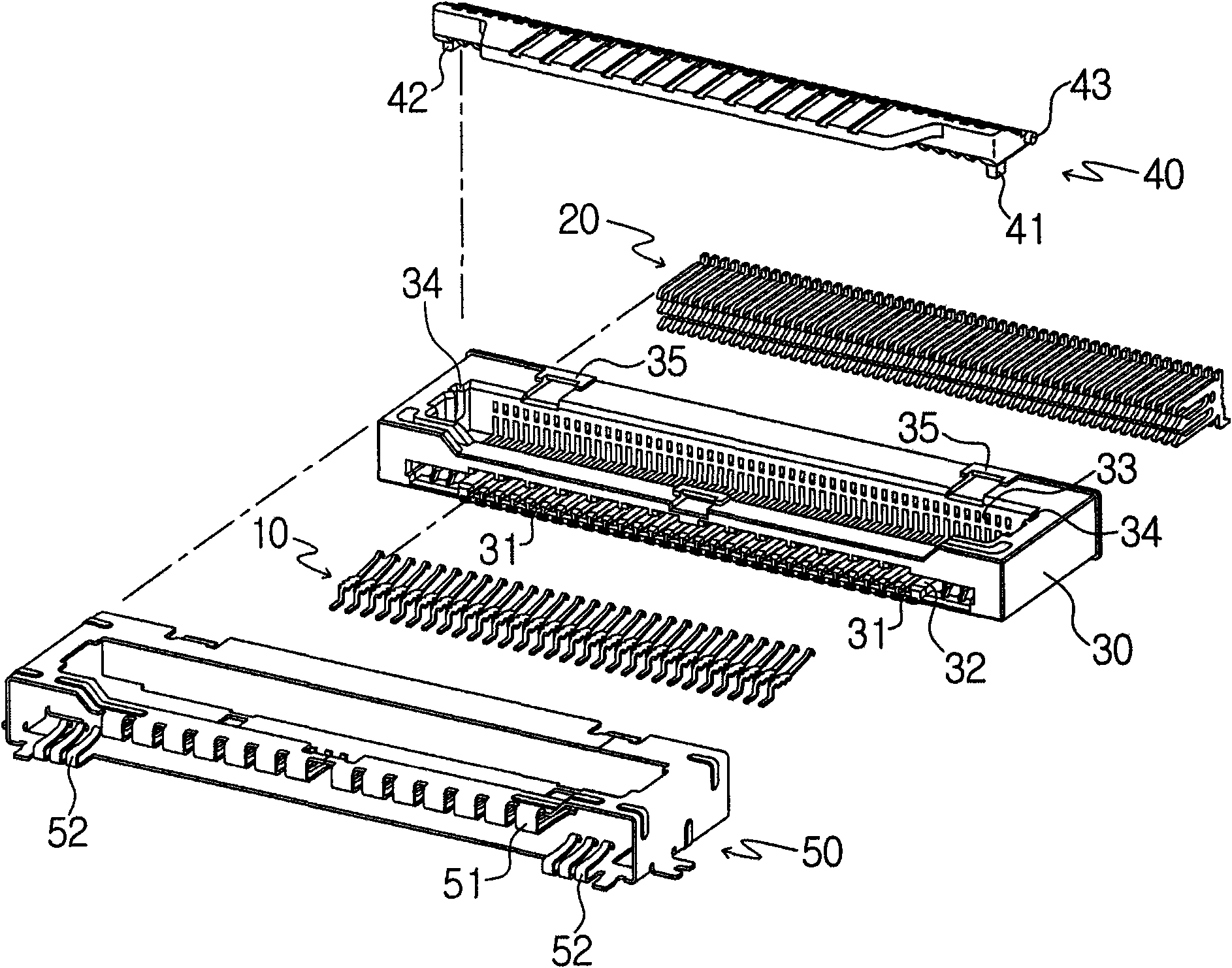
[0029] image 3 It is a schematic diagram of the disassembled state of the joint of the present invention. After the shell 30 is provided, the first terminal of the first terminal group 10 is inserted into the shell 30 from the socket direction through the first terminal socket 31 formed on the socket 32 ​​si...


PUM


Abstract

The invention relates to a connector, comprising a shell with an FPC / FFC jack; first, second terminal groups respectively inserted / arranged on the shell from the jack direction and the opposite direction of the jack; a brake supported by the terminal of the second terminal group; an outer cover, wherein the first terminals of the first terminal group are in '-' shape; the second terminal of the second terminal group comprises a rotary motion support part, a second contact part and an elastic support part at the end of the forked terminal arm; a cam of the brake is arranged between the rotary motion support part and the second contact part; the first, second terminals of the first, second terminal groups are arranged at different intervals; the outer cover comprises a first pressing part for pressing the FPC / FFC; the first terminals is linklocked with the first pressing part to make the upper surface of the first contact part contact with the corresponding terminal on the FPC / FFC lower surface; when the second contact part drops together with the rotation of the cam, the second terminal contacts with the corresponding terminal of the FPC / FFC upper surface inserted between the second contact part and the elastic support part.

Description

technical field [0001] The present invention relates to a joint, in particular, to a terminal that is pressurized by a brake or an outer cover to connect a flexible printed circuit board (FPC, Flexible Printed Circuit) or a flexible flat cable (FFC, Flexible Flat Cable) to a circuit board. connected connectors. Background technique [0002] Recently, as electronic products have become increasingly miniaturized, connectors are also required to be miniaturized, and the functions of electronic products are also becoming more diverse, requiring more transmission circuits. Therefore, connectors are also required to have multiple terminals. [0003] In order to have a plurality of terminals, if the terminals are arranged in one row, there is a limit to the miniaturization of the connector. Therefore, in many cases, the terminals are arranged in two rows. [0004] For example, if figure 1 As shown, Korean Registered Patent No. 443043 discloses a connector, which has a first termi...

Claims


Application Information

Patent Timeline
IPC IPC(8): H01R12/28H01R13/62H01R13/64H01R12/78H01R13/629
CPCH01R12/774H01R12/79H01R12/88H01R13/639
Inventor 李秀周崔正和
Owner UJU ELECTRONICS
Why Eureka
Try Eureka