Mounting structure of electronic device

An electronic device and mounting structure technology, applied in the field of diode mounting structure, can solve the problems of circuit electrical fault performance, instability, complicated operation, etc.

Inactive Publication Date: 2005-02-16
ALPS ALPINE CO LTD
View PDF1 Cites 2 Cited by
  • Summary
  • Abstract
  • Description
  • Claims
  • Application Information

AI Technical Summary

Problems solved by technology

[0010] However, in the structure of the conventional EGR sensor described above, when the diode 142 is mounted on the position sensor 102, since the diode 142 has polarity, an electrical failure may occur if the diode 142 is inserted in the reverse direction. Therefore, the operator must insert the diode 142 while confirming the direction. , which creates complex operational problems
[0011] In addition, if mis-insertion occurs, there will be a problem that electrical failure occurs in the circuit to make the performance unstable

Method used


Image

  • Mounting structure of electronic device
  • Mounting structure of electronic device
  • Mounting structure of electronic device

Examples


Embodiment Construction

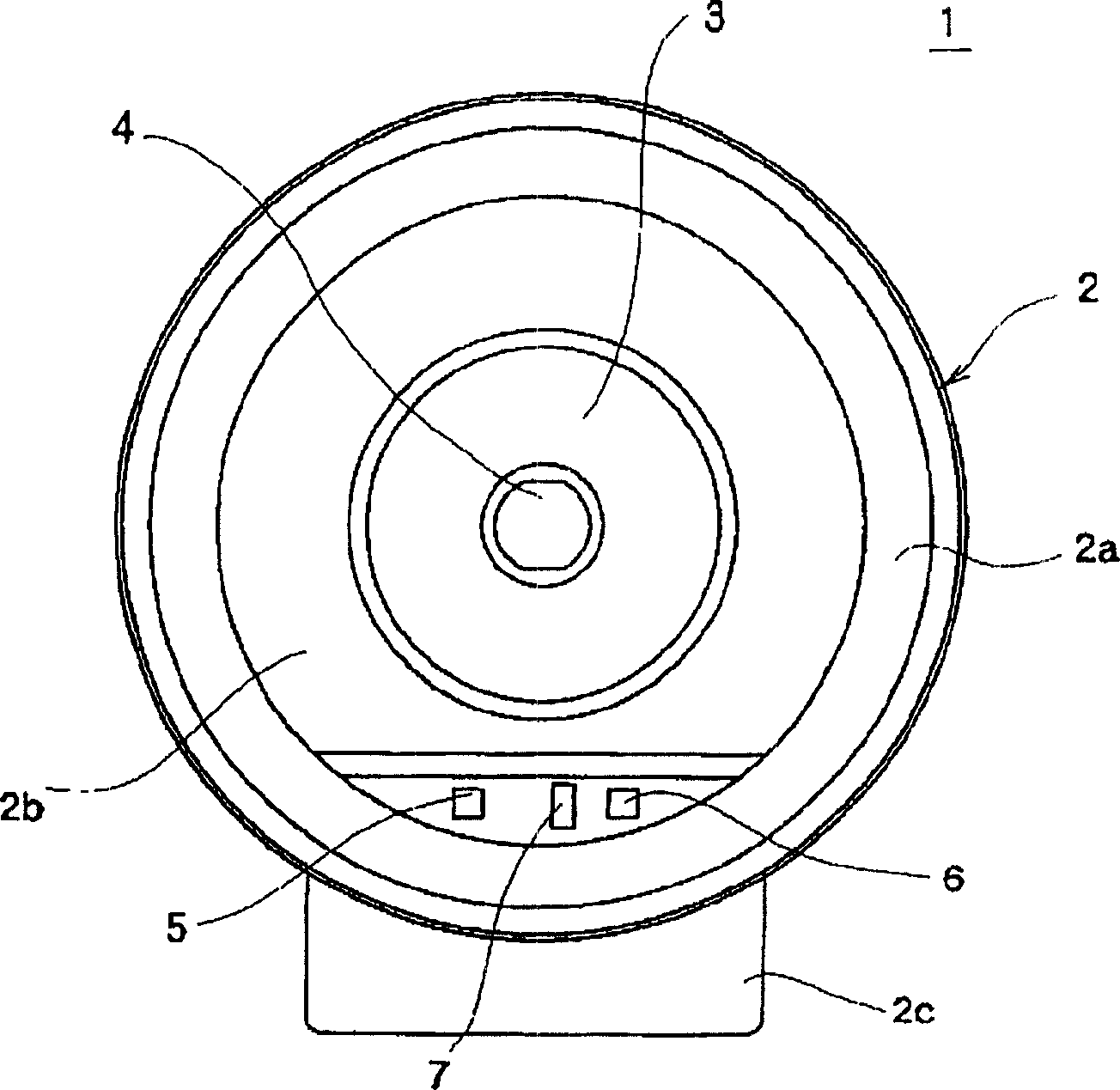
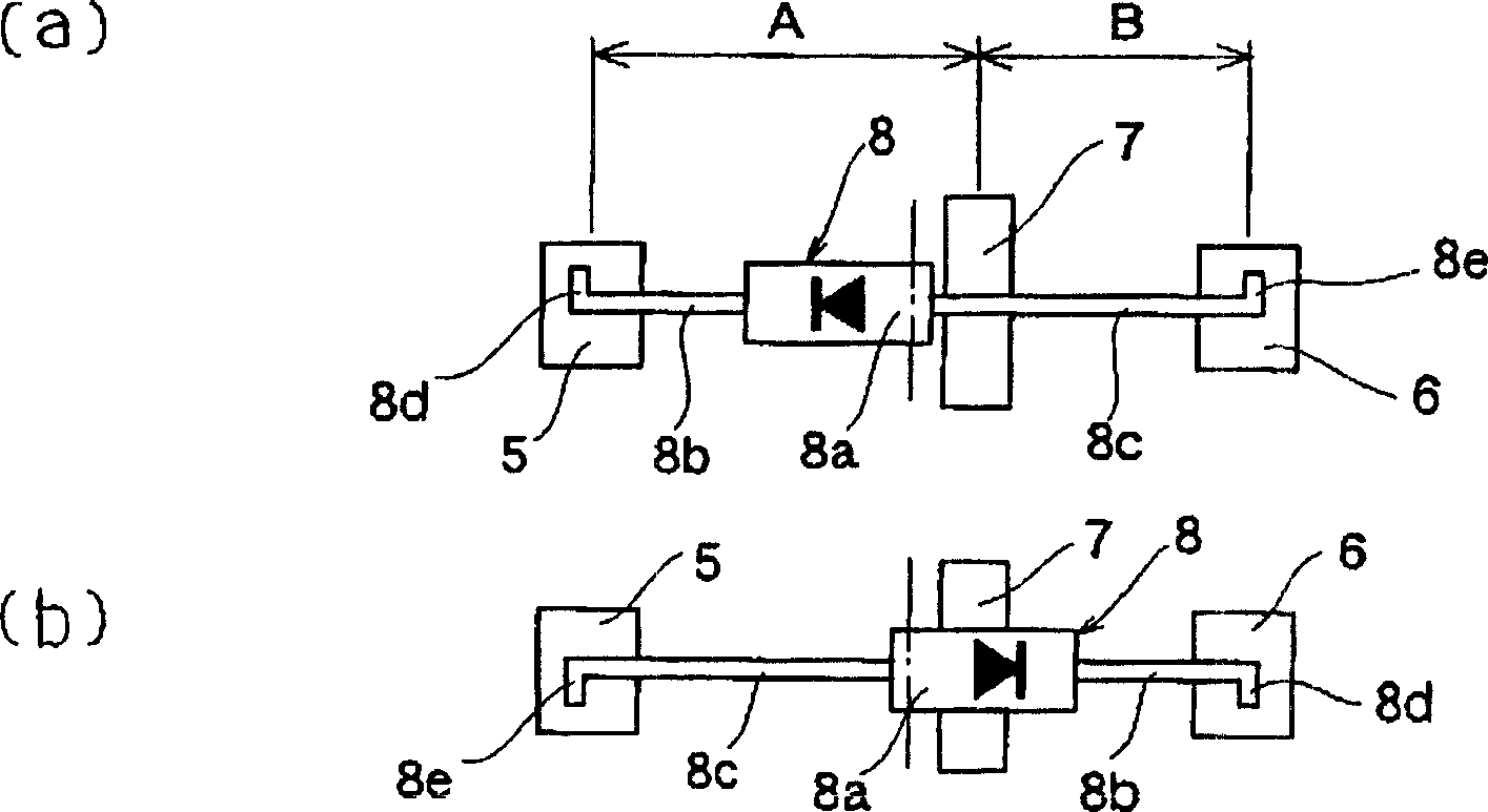
[0029] Below, according to Figure 1~3 Embodiments of the mounting structure of the electronic device of the present invention will be described in detail. figure 1 It is a front view showing the EGR sensor as the holding member of the mounting structure of the electronic device of the present invention, figure 2 It is an explanatory diagram showing the state where the electronic device is mounted on the holding member, (a) shows the state mounted in the normal position, (b) shows the state mounted in the reverse position, image 3 It is explanatory drawing of another Example which shows the state which mounted the electronic device on the holding member, (a) shows the state mounted in the normal position, (b) shows the state mounted in the reverse position.

[0030] exist figure 1 Among them, the EGR sensor 1 has a case 2 made of an insulating material such as synthetic resin, a cover body 3 covering the front surface of the case 2 and also made of an insulating material...


PUM


Abstract

The present invention provides an EGR sensor capable of preventing an electronic component having polarity, such as a diode, from being mounted in a reverse direction, of simplifying workability, and of preventing the generation of an electrical failure in a circuit. A structure for mounting an electronic component comprises: an electronic component 8 including an element portion 8a having polarity and a pair of lead terminals 8b and 8c; and a holding member 2 including a pair of electrode portions 5 and 6. The pair of lead terminals 8b and 8c of the electronic component 8 is formed to have different lengths, and an abutting portion 7 for positioning the element portion 8a of the electronic component 8 is provided in the holing member 2. The abutting portion 7 is formed between the pair of electrode portions 5 and 6 at a position leaning toward one of the electrode portions from their midpoint. When the electronic component 8 is mounted in the holding member 2 at a reverse position, the element portion 8a abuts to the abutting portion 7, and then at least one of the connection portions of the lead terminals is detached from one of the pair of the electrode portions 5 and 6.

Description

technical field [0001] The present invention relates to a position sensor (EGR sensor) of an EGR valve for controlling the amount of recirculation of exhaust gas of an automobile, and more particularly to a mounting structure of a diode inserted into the EGR sensor. Background technique [0002] As a conventional EGR valve device with a diode, it is known that a diode is connected in parallel to an excitation coil for driving an EGR valve for controlling the exhaust gas recirculation passage so as to constitute a parallel circuit in the valve device (for example, refer to Japanese Patent Laid-Open Publication No. 7-301155 bulletin). [0003] Next, the configuration of a conventional EGR valve device will be described based on the drawings. Figure 4 is a schematic sectional view of a conventional EGR valve device, Figure 5 is the circuit diagram of a linear solenoid of the same setup. [0004] exist Figure 4 Among them, the electric EGR valve device 101 is roughly divide...

Claims


Application Information

Patent Timeline
Patent Type & Authority Applications(China)
IPC IPC(8): H01L23/48H01R43/02
CPCH01R43/0263
Inventor 石原环次
Owner ALPS ALPINE CO LTD
Why Eureka
Try Eureka