
Twist and push mobile electronic device

An electronic device and mobile technology, which is applied in the direction of electrical equipment casing/cabinet/drawer, electrical components, casing/cabinet/drawer parts, etc., can solve the problem of difficult assembly of mobile electronic devices 1. Users are not comfortable , complex structure and other issues

Inactive Publication Date: 2015-08-26
麻天启
View PDF7 Cites 0 Cited by
  • Summary
  • Abstract
  • Description
  • Claims
  • Application Information

AI Technical Summary

Problems solved by technology

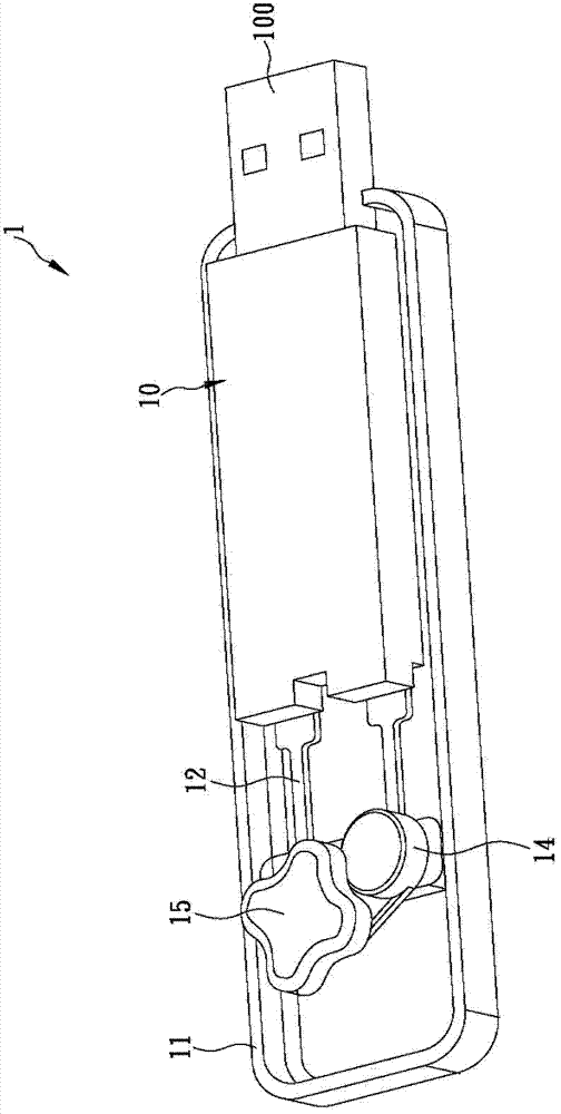
However, according to the research of the inventor, it is found that when the user uses this mobile electronic device 1, the angle of rotation of the rotating block 15 must reach 180 degrees in order to completely push the plug connector 100 out of the casing 11, which is too large. The rotation angle design is not smooth and quite inconvenient for the user
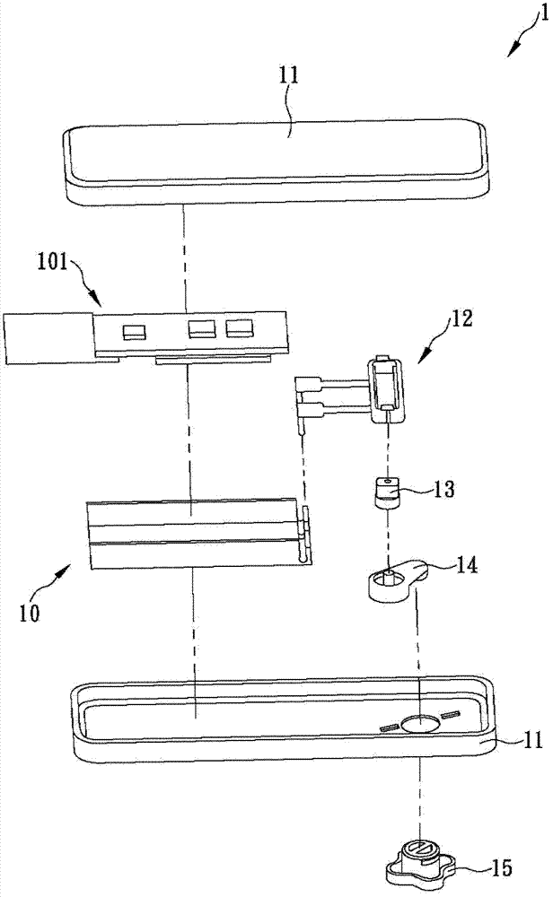
Moreover, the structure of the existing mobile electronic device 1 is too complex and the number of components is too large, so it is difficult for the manufacturer to assemble the mobile electronic device 1 in an automated manner, and the mobile electronic device 1 must be manufactured by manual assembly. , greatly increasing production costs
Furthermore, when the manufacturer assembles the mobile electronic device 1, the core element 10, the track element 12, the slider 13, the crankshaft 14 and the rotating block 15 must be assembled to the housing 11 one by one from different directions, which not only causes assembly The efficiency is low, and due to factors such as too many components, the possibility of assembly errors or mistakes is increased, resulting in an increase in the yield rate of the product, which is not ideal
Most importantly, because the structure of the existing mobile electronic device 1 is too complex, it is not conducive to the overall miniaturization of the device, resulting in the volume of the device is often difficult to meet the use and design requirements, which is very unsatisfactory

Method used


Image

  • Twist and push mobile electronic device
  • Twist and push mobile electronic device
  • Twist and push mobile electronic device

Examples


Embodiment Construction

[0044] In order to facilitate your examiner's further understanding and understanding of the purpose, structure and effects of the present invention, the following examples are given together with the drawings, and the detailed description is as follows.

[0045] The inventor has been engaged in the research and development and design of mobile electronic devices and other related fields for a long time, and found that the current mobile electronic devices that can push out the plug connector through the rotating structure often have the defects of too complicated structure and too many components, which leads to complicated assembly procedures , which is not conducive to automatic production, but also has problems such as low production efficiency. In addition, the user must rotate the rotating block to push out the plug connector, which is inconvenient to use. At present, although some operators have researched and improved the structure of the mobile electronic device in ord...


PUM


Abstract

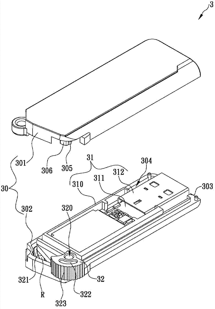
The invention discloses a rotating pushout type portable electronic device comprising a casing, a core element and a rotating rod. One side of the casing is provided with an opening and extends inwards to form a holding space. The core element is held in the holding space, and a connecting plug is arranged at the front end of the core element and corresponds to the opening. The position, adjacent to the rear end, of the core element is provided with a rail portion, and the position, adjacent to one end, of the rotating rod is pivotally arranged on the casing. One end of the rotating rod extends out of the casing. The position, adjacent to the other end, of the rotating rod is provided with a pushing portion which can be slidably arranged on the rail portion. According to the structure, a user can slightly rotate the rotating rod, so that the connecting plug can be quickly pushed out of the casing. Further, the rotating pushout type portable electronic device is simple in structure, so that manufacturers can manufacture the portable electronic device in an automatic assembly manner, production cost is greatly saved, and production efficiency can be improved.

Description

technical field [0001] The invention relates to a rotary push-out mobile electronic device. A core element is mainly arranged in a casing, and a rotating rod is pivotally arranged on the casing. A track portion is arranged near the rear end of the core element. When the rotating rod rotates, the pushing part can slide in the track part, and at the same time push or pull the core element, so that the plug joint at the front end of the core element can move to the outside or inside the casing. Background technique [0002] Currently, there are many small portable electronic devices on the market, such as Bluetooth adapters, flash drives, card readers, WiFi adapters, etc. Users can put it into their pockets and carry it with them. Most of these mobile electronic devices are provided with a core element (core element) in a casing. The so-called core element in the present invention mainly includes a circuit board and a plug connector. The circuit board can be a flash memory mod...

Claims


Application Information

Patent Timeline
Patent Type & Authority Patents(China)
IPC IPC(8): H05K5/00H05K5/02
Inventor 麻天启
Owner 麻天启
Learn More