Supercharge Your Innovation With Domain-Expert AI Agents!

Tensioning locking and lossless extending device

A technology of tensioning and wedge-shaped sliders, which is applied in the field of concrete components, can solve problems such as damage to concrete, loss of prestress, and loss of elongation, and achieve the effects of simple fabrication, convenient operation, and large-scale construction

Active Publication Date: 2013-04-03
CHINA RAILWAY NO 9 GRP
View PDF7 Cites 7 Cited by
  • Summary
  • Abstract
  • Description
  • Claims
  • Application Information

AI Technical Summary

Problems solved by technology

In recent years, the method of applying prestress first has also been used on a large scale in sleepers and CRTS II track slabs, but there have been some problems in the process of use, such as loss when the elongated prestress tendons are fixed with snap rings after the prestress is applied. For an elongation value of about 1 mm, it is necessary to over-stretch the ring by 1 to 3 mm to take out the snap ring, which will inevitably damage the concrete near the snap ring and lose part of the prestress.

Method used


Image

  • Tensioning locking and lossless extending device
  • Tensioning locking and lossless extending device
  • Tensioning locking and lossless extending device

Examples


Embodiment 1

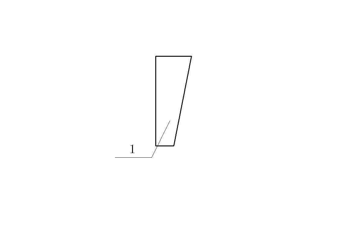
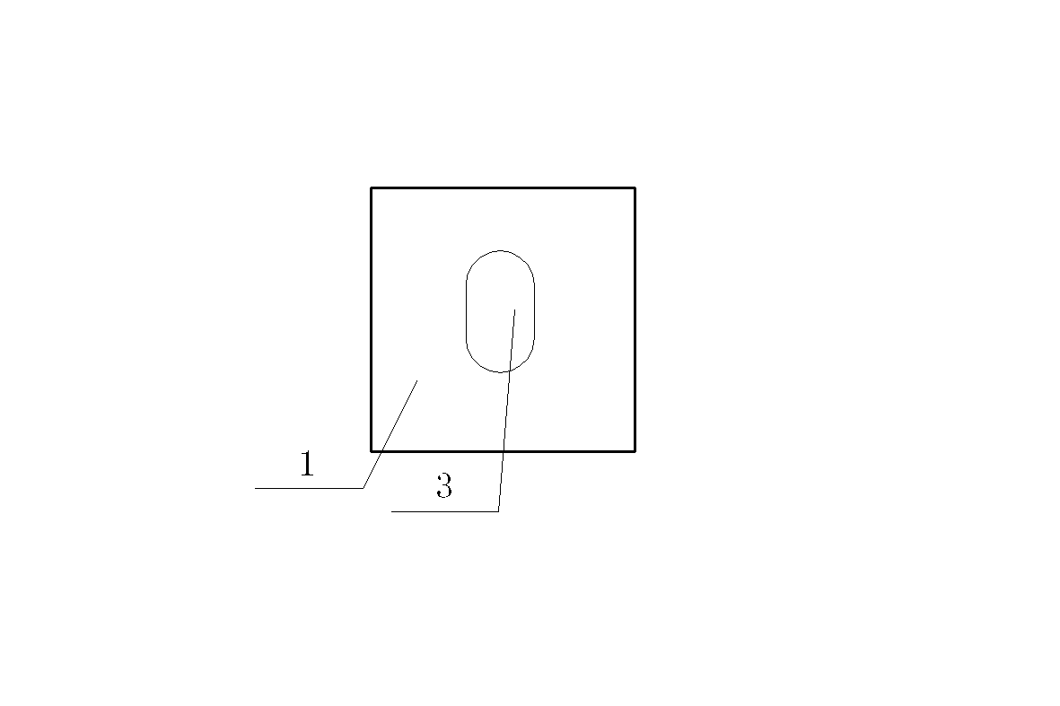
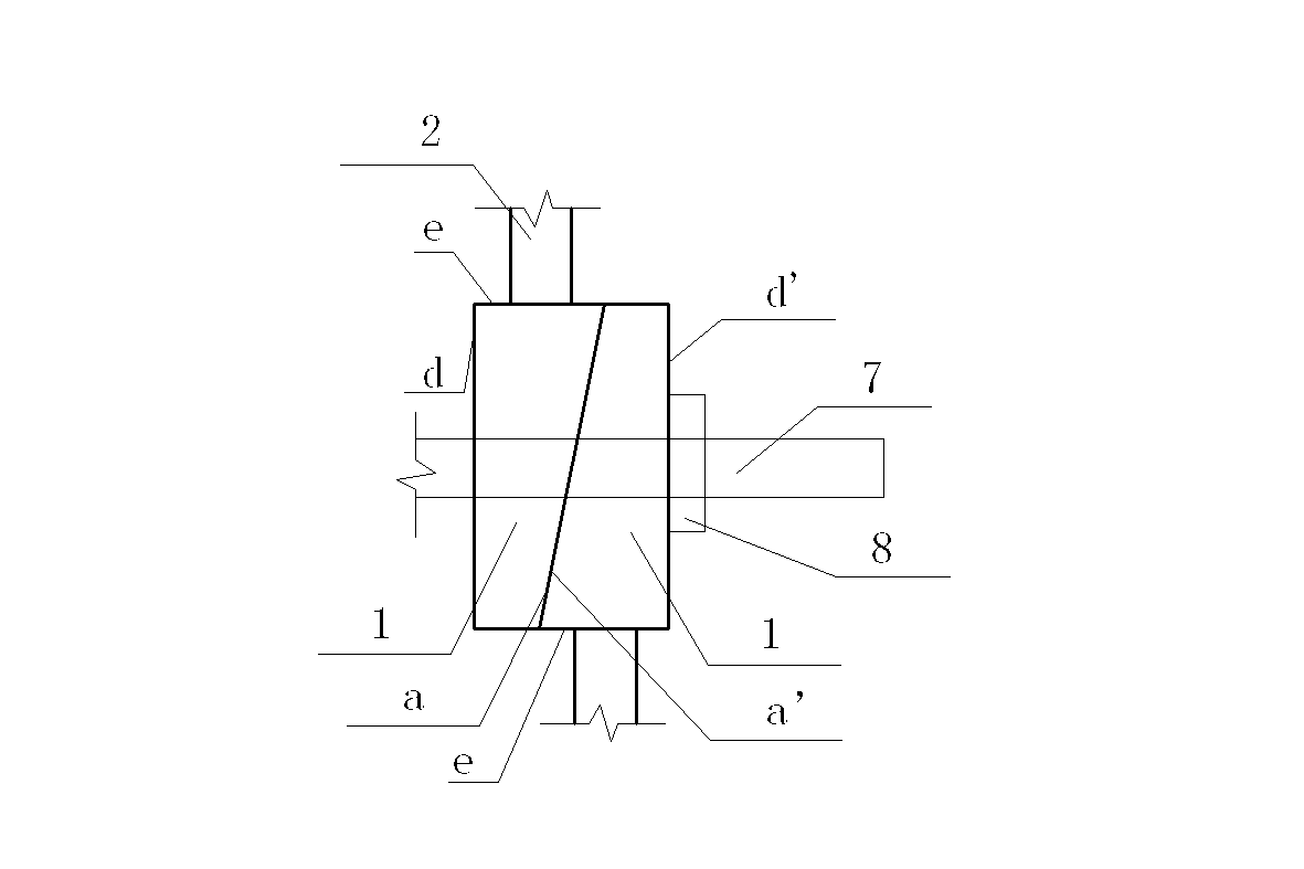
[0020] Embodiment 1: as Figure 1-4 As shown, a tension locking and non-destructive release device includes two wedge-shaped sliders I1 and two jacking bolts 2, and two wedge-shaped sliders I1 are formed with long holes 3, and two wedge-shaped sliders I1 Placed close to each other, the contact surfaces a and a' of the two wedge-shaped sliders I1 are inclined surfaces with complementary inclination angles, and the surfaces opposite to the contact surfaces a and a' of the two wedge-shaped sliders are vertical planes d and d' respectively, and the two wedge-shaped sliders I1 are respectively tightened by the tightening bolts 2, and the tightening bolts 2 are supported on the plane e of the wedge-shaped slider I1, and the plane e is a relatively wide plane perpendicular to the length direction of the elongated hole 3.

Embodiment 2

[0021] Embodiment 2: as Figure 5-10 As shown, a tension locking and non-destructive release device includes three wedge-shaped sliders and a jacking bolt 2, and the three wedge-shaped sliders are placed side by side in sequence. The three wedge-shaped sliders are divided into two types, of which One side of the wedge-shaped slider II5 located at both ends is a slope, and the opposite side of the slope is a vertical plane, on which a round hole 4 is formed, and both sides of the wedge-shaped slider III6 in the center are slopes, and a long hole is formed on it. Bar hole 3; the contact surfaces a, a', b, b' of the adjacent wedge-shaped sliders are inclined surfaces with complementary inclination angles, and the centered wedge-shaped slider III6 is tightened by the tightening bolt 2, which is pressed against the wedge-shaped slider. On the plane f of the block III6, the plane f is a relatively wide plane perpendicular to the length direction of the long hole 3 .

Embodiment 3

[0022] Embodiment 3: as Figure 11 , 12 As shown, a tension locking and non-destructive release device includes four wedge-shaped sliders and two jacking bolts 2, and each wedge-shaped slider is placed side by side in sequence. Embodiment 3, the inside of the wedge-shaped slider II5 positioned at both ends is a slope, and the outside is a vertical plane, on which a round hole 4 is formed; the two sides of the wedge-shaped slider III6 located in the middle are slopes, and the sides are formed on it. There are elongated holes 3, and the contact surfaces a, a', b, b', c, c' of the adjacent wedge-shaped sliders are inclined surfaces with complementary inclination angles, and the two tightening bolts 2 respectively push against the two wedge-shaped sliders in the middle. On the plane f of the block III6, the plane f is a relatively wide plane perpendicular to the length direction of the long hole 3 .

[0023] There are two stages in use, the first stage is the tension locking sta...


PUM


Abstract

The invention relates to a tensioning locking and lossless extending device. The structure of the tensioning locking and lossless extending device comprises two wedge-shaped sliding blocks and two puller bolts; long holes are formed in the two wedge-shaped sliding blocks; the two wedge-shaped sliding blocks are arranged in a clinging way; contact surfaces of the two wedge-shaped sliding blocks are inclined planes which are parallel with each other; planes opposite to the two inclined planes are vertical planes; and the two puller bolts respectively press against the upper bottom surface and the lower bottom surface of the two wedge-shaped sliding blocks. By adopting the structure, when tensioning, through combination of the sliding blocks, the sliding blocks are located by the puller bolts to lock; when extending, a middle sliding block slides outwards by loosening pressing nuts, then the overall thickness of the device is reduced, so that the aim of extending is realized. The device can be applied to track boards, beams and other similar engineering in a pretensioning method operation, and has the advantages of simplicity and easiness in manufacturing, convenience and rapidness in operation, convenience in large-scale construction and the like.

Description

technical field [0001] The invention relates to a concrete member suitable for single prestressed pretensioning construction, specifically a device for tension locking and tension release. Background technique [0002] With the rapid development of social economy, the construction of national infrastructure such as kilometers, railways, and bridges has also encountered new developments. Compared with general structures, prestressed structures are gradually being used on a large scale in the engineering field due to their advantages such as good mechanical performance, large service span, good durability, and light weight. The application of prestress is divided into two methods: first application and later application. The post-tensioning method is mostly used in concrete prefabricated parts, such as prefabricated beams and prefabricated slabs. In recent years, the method of applying prestress first has also been used on a large scale in sleepers and CRTS II track slabs, bu...

Claims


Application Information

Patent Timeline
Patent Type & Authority Applications(China)
IPC IPC(8): B28B23/04
Inventor 贾有权王培董凤龙潘宏刘占伟王露鸣付国财
Owner CHINA RAILWAY NO 9 GRP
Features
  • R&D
  • Intellectual Property
  • Life Sciences
  • Materials
  • Tech Scout
  • Unparalleled Data Quality
  • Higher Quality Content
  • 60% Fewer Hallucinations
Learn More