
Bridge crane power supply sliding antenna device and current collector installation fixing device thereof

A bridge crane and fixing device technology, applied in the field of trolley line, can solve the problems of inability to guarantee the contact pressure, smooth sliding of the current collector slider and the trolley line plane, poor contact between the collector and the trolley line guide rail, etc. Effect of contact pressure regulation

Active Publication Date: 2014-12-17
PANGANG GRP ENG TECH
View PDF8 Cites 0 Cited by
  • Summary
  • Abstract
  • Description
  • Claims
  • Application Information

AI Technical Summary

Problems solved by technology

[0003] Although the current collector itself can adjust the contact pressure between the slider and the trolley line by adjusting the spring tension in the prior art, in the actual operation process, due to the influence of environmental factors or installation conditions, the adjustment of the current collector itself sometimes The proper contact pressure cannot be guaranteed, which will lead to poor sliding between the collector slider and the trolley wire plane and poor contact between the collector and the trolley wire guide rail

Method used


Image

  • Bridge crane power supply sliding antenna device and current collector installation fixing device thereof
  • Bridge crane power supply sliding antenna device and current collector installation fixing device thereof
  • Bridge crane power supply sliding antenna device and current collector installation fixing device thereof

Examples


Embodiment Construction

[0018] Hereinafter, a power supply trolley line device for an overhead crane and a collector installation and fixing device thereof according to exemplary embodiments of the present invention will be described in detail with reference to the accompanying drawings.

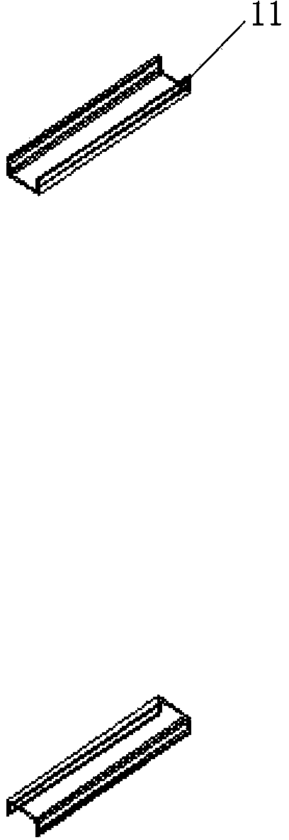
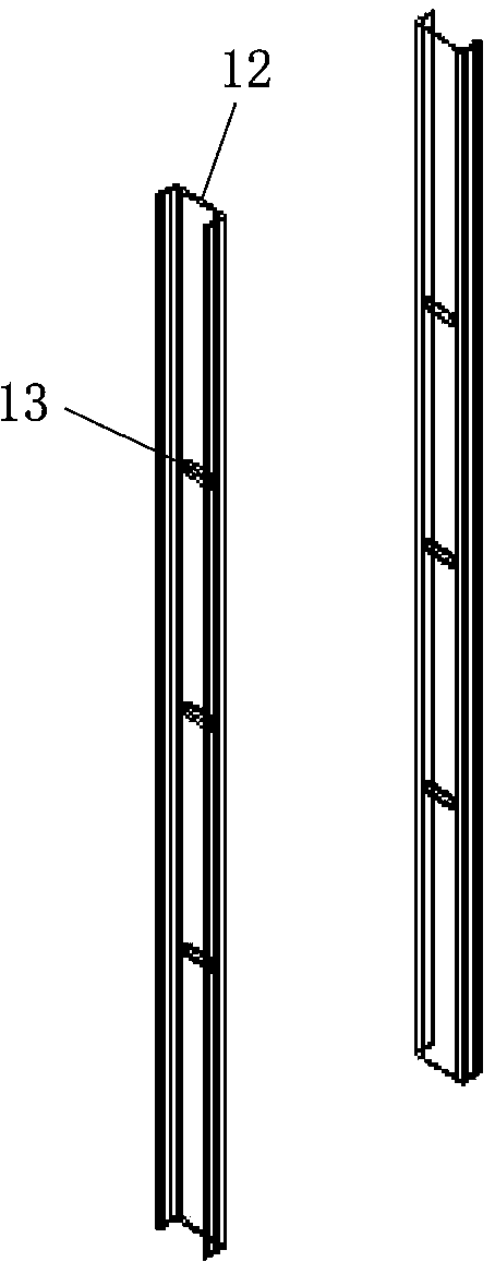
[0019] Figure 1A to Figure 1C A schematic structural view showing a fixing unit in a current collector installation and fixing device according to an exemplary embodiment of the present invention; Figure 2A A schematic structural view showing a current collector bracket in a current collector installation and fixture device according to an exemplary embodiment of the present invention; Figure 2B A schematic structural view showing a current collector installation and fixing device according to an exemplary embodiment of the present invention; image 3 show Figure 2B Partial enlarged schematic diagram of part I in .

[0020] like Figure 1A to Figure 3 As shown, in an exemplary embodiment of the present inven...


PUM


Abstract

The invention provides a bridge crane power supply sliding antenna device and a current collector installation fixing device thereof. The current collector installation fixing device comprises a current collector support, a fixed unit and a long round hole connecting piece, wherein the fixed unit is a rectangular frame which is composed of a transverse part with a plate strip shape and a longitudinal part, and the longitudinal part is provided with a first long round hole; the length direction of the first long round hole is vertical to that of the longitudinal part, the current collector support is arranged in the fixed unit, and a flange plate contacted with the current collector support and the longitudinal part is provided with a second long round hole which is corresponding to the first long round hole of the longitudinal part; and the long round hole connecting piece passes through and is connected with the first long round hole and the second long round hole, and the relative position of the current collector support and the fixed unit can be adjusted along the length direction of the first long round hole. The device provided by the invention can realize the adjustment of contact pressure between a sliding block and a sliding antennae body through adjusting the position of the current collector support.

Description

technical field [0001] The present invention relates to the technical field of trolley lines of bridge cranes, more specifically, to a current collector installation and fixing device for adjusting the contact pressure between the collector slider and the trolley line of bridge cranes and a device comprising The collector is installed as a fixed device for the trolley line device of the overhead crane power supply. Background technique [0002] Generally, bridge cranes, also known as beam cranes, are hoisting equipment that are placed horizontally over workshops, warehouses and stockyards for material lifting. Because its two ends are located on tall concrete pillars or metal supports, it is shaped like a bridge, so it is called a bridge crane. The bridge frame of the bridge crane runs longitudinally along the tracks laid on the elevated sides on both sides, which can make full use of the space under the bridge frame to lift materials without being hindered by ground equipm...

Claims


Application Information

Patent Timeline
Patent Type & Authority Patents(China)
IPC IPC(8): B66C13/12
Inventor 何乐平何再勇夏登奎
Owner PANGANG GRP ENG TECH
Learn More