Stand column supporting fabric shade type dryer

A clothes dryer and cloth cover type technology, which is applied in the field of column-supported cloth cover type clothes dryers, can solve the physical injury of the operator, easily touch the cover body part located at the outer edge of the safety plate, and the clothes dryer is placed Instability and other problems, to achieve the effect of convenient disassembly and assembly

Active Publication Date: 2013-04-03
胡杰波
View PDF4 Cites 7 Cited by
  • Summary
  • Abstract
  • Description
  • Claims
  • Application Information

AI Technical Summary

Problems solved by technology

However, the above-mentioned integrally rigid safety disk or annular ring, when stored, needs an enlarged packing case for packing due to the limited change in outer diameter, which results in a large increase in production and transportation costs; in addition, users use In this case, since the rigid safety disc or annular ring cannot be seen outside the cover, and the outer edge of the rigid safety disc extends to the inner peripheral surface of the cover, if the operator is not careful when using it, the operator's legs and feet will be extremely damaged. It is easy to touch the cover body located at the outer edge of the safety plate. In this way, on the one hand, after the outer edge of the safety plate is hit by the human body, the impact force will be directly transmitted to the support column or the cover body located on the safety plate through the plate surface of the safety plate. All parts at the outer edge, resulting in the overall instability of the dryer, or even toppling over; on the other hand, because the structure of the safety plate is rigid, such a collision may also cause injury to the operator's body

Method used


Image

  • Stand column supporting fabric shade type dryer
  • Stand column supporting fabric shade type dryer
  • Stand column supporting fabric shade type dryer

Examples


no. 1 example

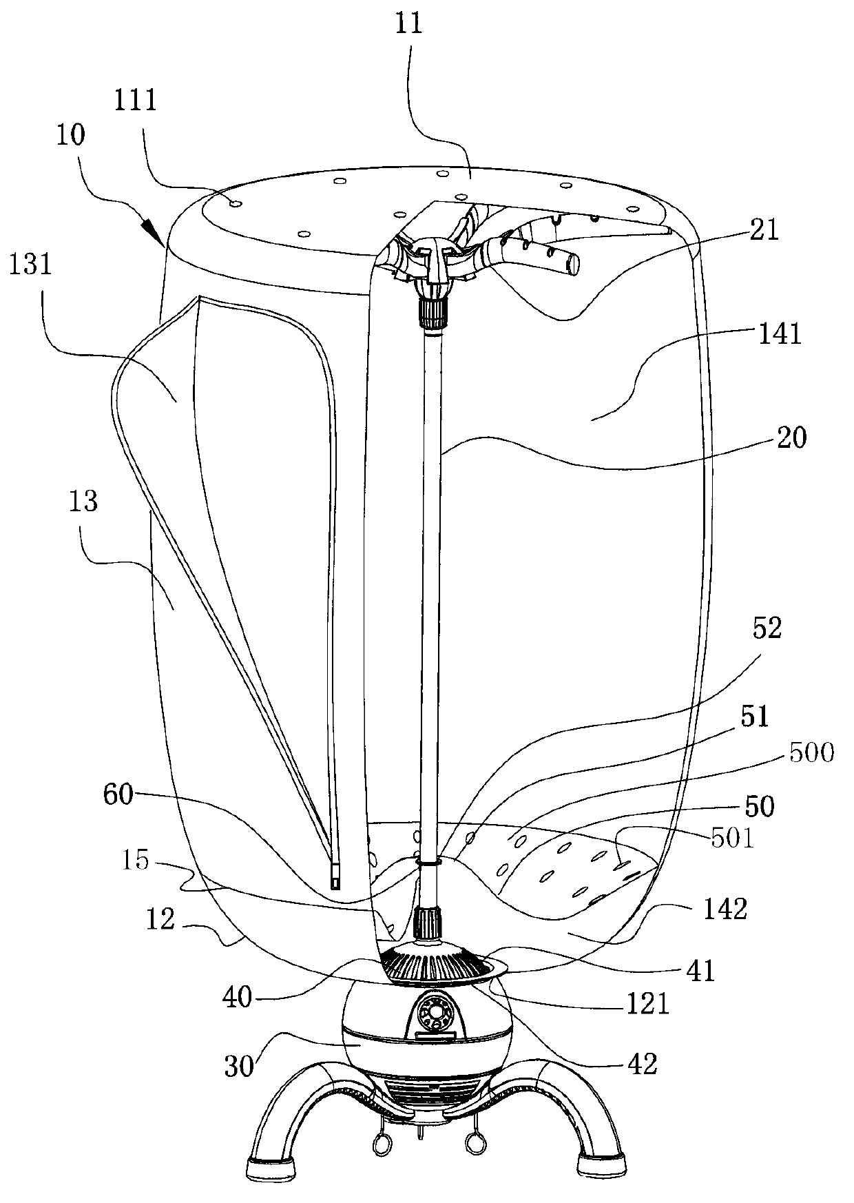
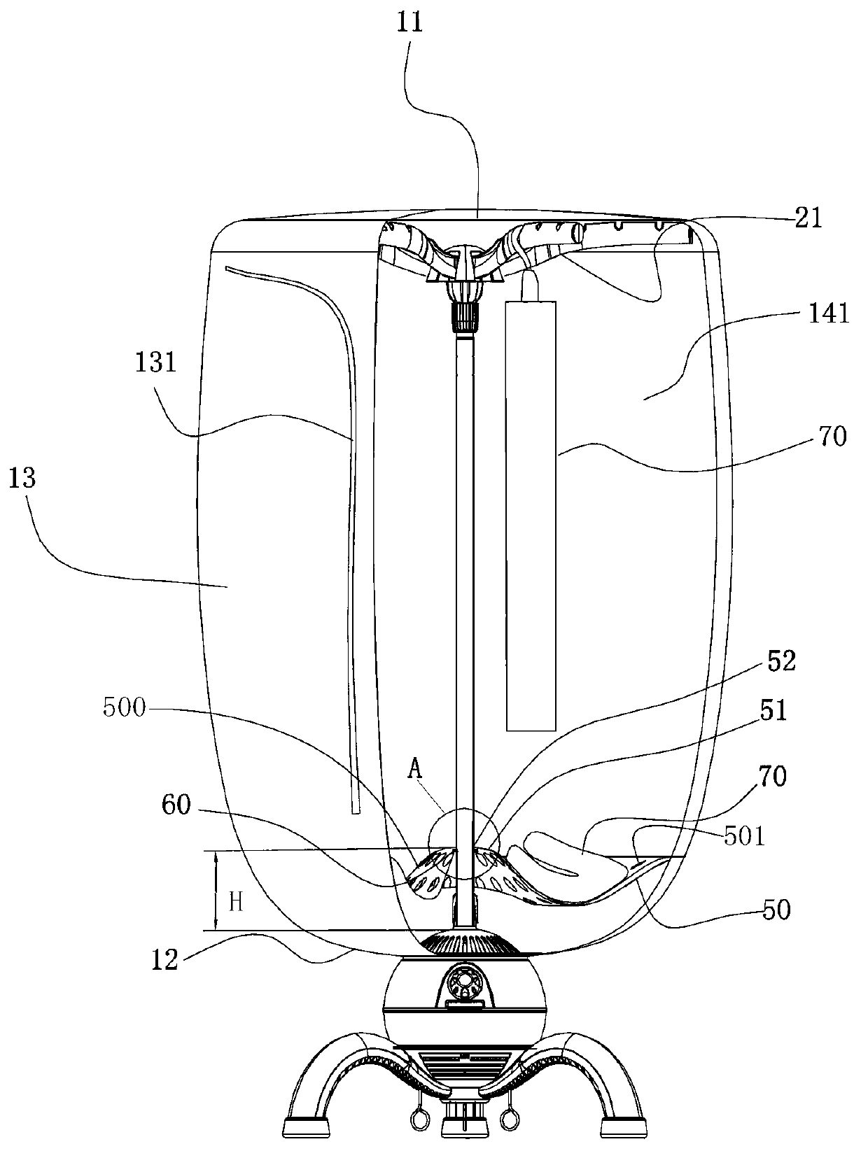
[0045] like figure 1 , Figure 2A , Figure 2B Shown is a column-supported cloth hood dryer in a preferred embodiment of the present invention, the dryer includes a hot air generator 30, and an air outlet shed 40 with multiple air outlets 41 located on the hot air generator 30 , the lower part is supported on the air outlet shed 40, the upper part is connected with the column 20 of the umbrella support frame 21, the cloth cover 10 supported on the umbrella support frame 21, the cloth cover 10 has a top surface 11, a lower bottom surface 12 and a longitudinal peripheral surface 13. The top surface 11 is supported on the umbrella-shaped support frame 21, the longitudinal peripheral surface 13 surrounds the column 20, and the central opening 121 of the lower bottom surface 12 is connected to the air outlet shed 40. Wherein, the bottom of the air outlet shed 40 is connected with the upper casing 42 of the hot wind generator 30, and a circle of grooves is formed at the connection...

no. 2 example

[0058] In order to make the isolation unit 50 of the present invention fold together with the cloth cover 10 into a smaller volume, softer and thinner fabrics are preferably used, so preferably, the aperture of the isolation channel 501 is set larger or the isolation channel 501 is arranged The ground is relatively dense, especially when the isolation unit 50 is only made of a flexible mesh cloth. Such isolating unit 50 is less resistant to tensile deformation on the plane, and its strength cannot be guaranteed. The distance between the clothing and the air outlet 41 will be difficult to control.

[0059] Optionally, as in Figure 4A As shown, the isolation unit 50 is evenly provided with a plurality of flexible anti-pull cloth strips 56 for preventing the isolation unit 50 from being stretched and deformed along the circumferential direction from the through hole 52 to the outer peripheral edge, and is used to prevent the isolation unit 50 from being stretched and deformed. ...

no. 3 example

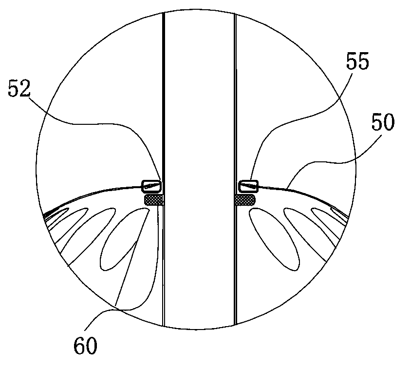
[0066] like Figure 5A , 5BAs shown, the longitudinal positioning device 60 is provided with a connection portion connected to the middle portion 51 of the isolation unit 50 . Optionally, the connecting portion is a hole 611 arranged at intervals along the periphery of the longitudinal positioning device 60, and the periphery of the through hole 52 of the isolation unit 50 is provided with a hook 511 that can penetrate into the hole 611. After the hook 511 penetrates into the hole 611, the isolation The central part 51 of the unit 50 is fixed on the longitudinal positioning means 60 . Since the hook 511 and the hole 611 are detachably connected, the disassembly and assembly between the two is relatively simple.

[0067] It is worth noting that the connection between the vertical positioning device 60 and the middle part 51 is not limited to the structure of this embodiment, for example, the vertical positioning device 60 may also include a hook fixed on the column 20, and th...


PUM


Abstract

A stand column supporting fabric shade type dryer comprises a hot air generator, an air outlet shed provided with an air outlet, a stand column, a fabric shade, a longitudinal positioning device arranged on the stand column and spaced from the air outlet shed for a certain distance, and a piece-shaped isolation unit positioned above a lower bottom surface, made of a flexible material and provided with an air circulation part, wherein the peripheral edge of the isolation unit is connected to the longitudinal peripheral surface of the fabric shade; a through hole is formed in the middle of the isolation unit, and penetrates the stand column, and the middle part is positioned on the longitudinal positioning device; a drying room is arranged between the isolation unit and a top surface; and an isolation room is arranged between the isolation unit and the lower bottom surface. At the same time of providing the safe drying room, the peripheral edge of the isolation unit is collided by legs of an operator body to have no influence on stability maintenance of the dryer and to have no harm to collided skin surfaces of the operator body; and the isolation unit made of the flexible material can be rolled to various shapes along with the fabric shade, so that the packaging volume is basically not influenced; and the dryer further has the convenience in dismounting.

Description

technical field [0001] The invention relates to a clothes dryer, in particular to a column-supported cloth-hood dryer. Background technique [0002] The traditional cloth hood dryer supported by columns, in order to prevent the clothes hanging in the drying room from accidentally slipping and cover the air outlet or to separate the lower end of the hanging clothes from the air outlet by a certain distance, so as to improve the safety of drying clothes. No. 200710079213.8 discloses a shed-type clothes dryer with a safety plate, which improves the interior of the drying chamber. A ventilated safety plate is provided on the air outlet shed. The outer diameter of the safety plate matches the inner peripheral surface of the cover, and the ventilated safety plate The drying room is divided into an upper drying room and a lower hot air tempering room. [0003] The above-mentioned safety plate adopts the following two structures: the first type of safety plate is rigid as a whole, ...

Claims


Application Information

Patent Timeline
Patent Type & Authority Applications(China)
IPC IPC(8): D06F58/10D06F58/20
Inventor 胡杰波
Owner 胡杰波
Why Eureka
Try Eureka