Screwed bolt positioning chimney

A chimney and fit technology, applied in the field of double-layer stainless steel thermal insulation chimneys, can solve the problems that the bite hooks cannot realize the full waterproof function, the curling seam structure is not very perfect, and reduce the thermal insulation performance of the chimney, etc., so as to achieve convenient installation and confirmation work, save the flanging process, and reduce the effect of maintenance costs

Active Publication Date: 2015-06-17
天津云白环境设备制造有限公司
View PDF5 Cites 0 Cited by
  • Summary
  • Abstract
  • Description
  • Claims
  • Application Information

AI Technical Summary

Problems solved by technology

[0002] In the existing chimney products, the tooth shape of the head and bottom cover is manufactured by cutting the cylindrical surface. The disadvantage is that there is a convection channel between the outer pipe of the chimney section and the thermal insulation material. On the one hand, the thermal insulation performance of the chimney is reduced. On the other hand, the condensed water that may be produced will enter the inner pipe of the chimney; the existing chimney products, the crimping structure of the outer pipe and the head and bottom cover is not very perfect, and its shortcoming is the snap hook of the outer pipe and the head and bottom cover The reliability is poor, the ability to bear axial load is low, and the full waterproof function cannot be realized at the bite hook, which provides a channel for rainwater to enter the insulation layer between the inner and outer pipes; the existing chimney products, after the head and bottom cover are screwed together There is a problem that it is difficult to confirm whether the screwed position is in place, and there is also the problem of automatic loosening due to thermal expansion and contraction of the chimney section, and there are design deficiencies

Method used


Image

  • Screwed bolt positioning chimney
  • Screwed bolt positioning chimney
  • Screwed bolt positioning chimney

Examples


Embodiment Construction

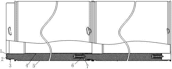
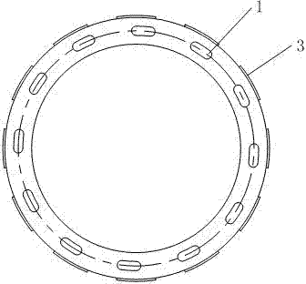
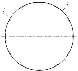
[0014] Such as figure 1 , figure 2 , image 3 , Figure 4 As shown, the chimney is positioned by the screw-in type bolt, which consists of an inner pipe 4 and an outer pipe 5. There is a gap between the inner pipe 4 and the outer pipe 5 and an insulation layer is arranged in the gap. The top and bottom ends of the double-layer stainless steel heat preservation chimney are A head cover 1 and a bottom cover 7 are provided respectively, one side wall of the head cover 1 is welded and fixed with the inner tube 4, the other side wall of the head cover 1 is fixed with the outer tube 5 through crimping, and the outer side of the head cover 1 The wall has at least eight screwing teeth 3 evenly distributed along the circumference, and the same number of pits 2 as the screwing teeth are uniformly distributed on the surface of the head cover 1 along the circumference, and the position of the pits 2 is the same as that of the screwing teeth. 3 are in the same position, one side wall o...


PUM


Abstract

The invention provides a screwed bolt positioning chimney. The top and bottom ends of the chimney are respectively provided with a head cover and a bottom cover. One side wall of the head cover is fixed with an inner tube, while the other side wall of the head cover is fixed with an outer tube through crimping engagement. A plurality of screwing teeth are uniformly distributed along the circumference of the outer side wall of the head cover. Pits same with the screwing teeth in number are uniformly distributed along the circumference of the surface of the head cover. The pits are consistent with the screwing teeth in position. One side wall of the bottom cover is fixed with the inner tube, while the other side wall of the bottom cover is fixed with the outer tube through crimping engagement. Screwing teeth same with the head covers in number are uniformly distributed along the circumference of the inner side wall of the bottom cover, and positioning elastic bolts same with the pits in number are uniformly distributed along the circumference of the bottom cover. With adoption of the crimping engagement structure, water in the tube or dew outside the outer tube is blocked, and the loosening problem is solved by using the positioning elastic bolts and screwing teeth, so that the using safety is ensured.

Description

technical field [0001] The invention relates to a double-layer stainless steel heat-insulating fireplace chimney, in particular to a double-layer stainless steel heat-insulation chimney with positioning elastic bolts and screwing teeth. Background technique [0002] In the existing chimney products, the tooth shape of the head and bottom cover is manufactured by cutting the cylindrical surface. The disadvantage is that there is a convection channel between the outer pipe of the chimney section and the thermal insulation material. On the one hand, the thermal insulation performance of the chimney is reduced. On the other hand, the condensed water that may be produced will enter the inner pipe of the chimney; the existing chimney products, the crimping structure of the outer pipe and the head and bottom cover is not very perfect, and its shortcoming is the snap hook of the outer pipe and the head and bottom cover The reliability is poor, the ability to bear axial load is low, ...

Claims


Application Information

Patent Timeline
Patent Type & Authority Patents(China)
IPC IPC(8): F23J11/00
Inventor 王泳康平贺福全
Owner 天津云白环境设备制造有限公司
Why Eureka
Try Eureka