Floor in cab as well as drawing process and die for floor

A drawing die and cab technology, which is applied to the floor in the cab and its drawing process and die fields, can solve the problems of high die development cost, increased flanging process, large size, etc., so as to improve the utilization rate of materials and save money. The effect of development cost and processing convenience

Inactive Publication Date: 2015-09-02
ANHUI JIANGHUAI AUTOMOBILE GRP CORP LTD
View PDF8 Cites 2 Cited by
  • Summary
  • Abstract
  • Description
  • Claims
  • Application Information

AI Technical Summary

Problems solved by technology

After the second step is leveled, the size required in the length direction of the sheet is larger, and the material utilization rate is low, which is about 59.31%.
In addition, the flanging process is added, and the mold development cost corresponding to this process is relatively high, and the traces produced by the flanging cannot be flattened

Method used


Image

  • Floor in cab as well as drawing process and die for floor
  • Floor in cab as well as drawing process and die for floor
  • Floor in cab as well as drawing process and die for floor

Examples


Embodiment Construction

[0040] In order to enable those skilled in the art to better understand the technical solution of the present invention, the solution of the present invention will be further described in detail below in conjunction with specific embodiments.

[0041] The floor drawing process in the cab provided by the embodiment of the present invention includes the following steps:

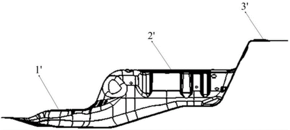
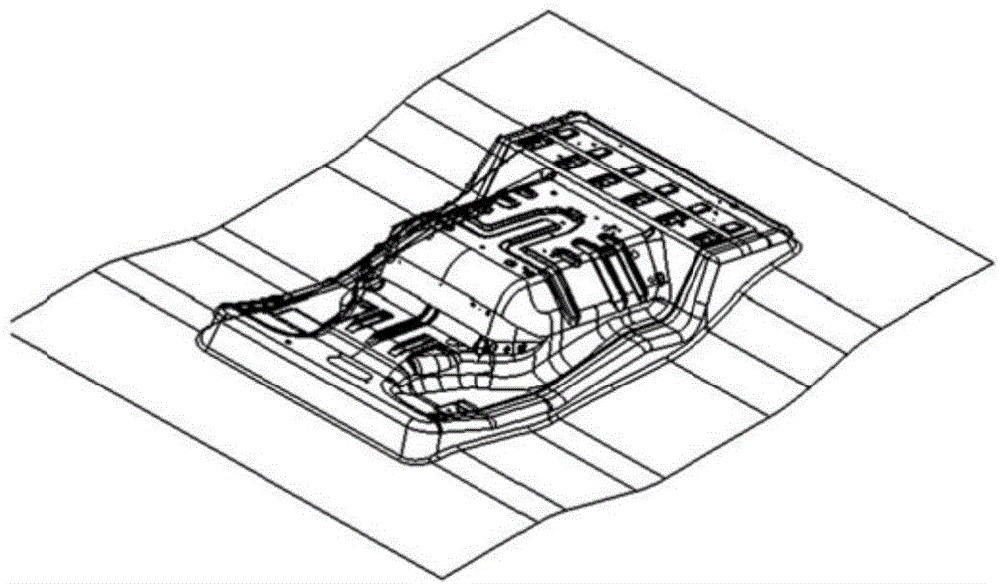
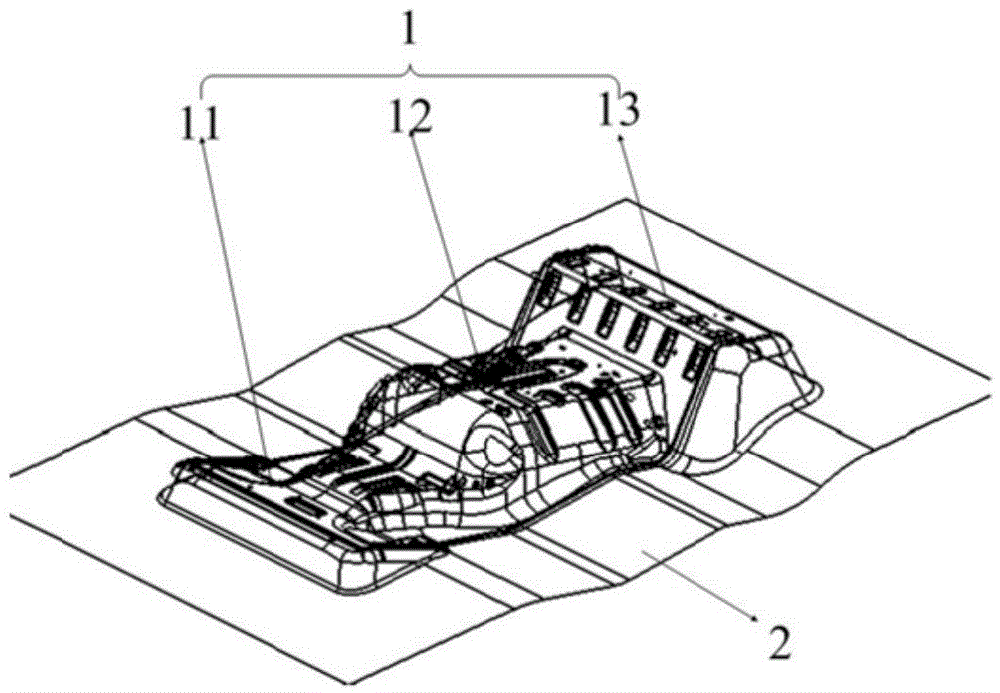
[0042] OP10: drawing, using a drawing die with a draft angle of 30°-45° at the deepest drawing point and a follow-up surface on the binder surface, drawing the sheet once to form a stepped three-convex platform on the floor of the cab structure;

[0043] OP20: trimming, trimming the surrounding edges of the formed parts;

[0044] OP30: Punching, side punching, punching the front hole and side hole of the trimmed part.

[0045] Compared with the prior art, the drawing process provided in the embodiment of the present invention omits the process of flanging, and the plate is drawn and formed at one time to form...


PUM


Abstract

The invention relates to the technical field of drawing and discloses a drawing process of a floor in a cab. The drawing process comprises three steps of drawing, trimming and punching and side punching, a drawing die with the draft angle of the deepest drawing position ranges from 30 degrees to 45 degrees and a binder surface used as a profile is adopted for one-time drawing, the flanging procedure is omitted, the development cost of a flanging die is saved, and the material utilization rate is increased. The invention further discloses the drawing die applied to the process. A female die comprises a first boss surface, a second boss surface and a third boss surface which are distributed in a step shape and are in one-to-one correspondence with bosses on the floor in the cab, and the draft angle of the third boss surface ranges from 30 degrees to 45 degrees; the circumferential edge of the female die is connected with the binder surface which is a bent surface changing along with the edge profile of the floor in the cab. With the adoption of the die, one-time drawing of the floor in the cab can be realized, and the facade of the floor can be prevented from being broken. Finally, the invention further discloses the floor, prepared with the process, in the cab.

Description

technical field [0001] The invention relates to the technical field of drawing, in particular to a floor in a driver's cab, its drawing process and a mold. Background technique [0002] refer to figure 1 , is a schematic diagram of the structure of the floor in the cab of a truck, which includes the first boss 1', the second boss 2' and the third boss 3' connected in sequence, and the three bosses are distributed in steps, among which The elevation height of the highest third boss 3' is 410mm. Due to the large depth of the product, it is difficult to draw and form, and it is easy to cause cracks at the facades of steps at all levels. [0003] In order to solve the above-mentioned problem of floor molding, the method adopted in the prior art is to flatten the two-level steps formed by the second boss 2' and the third boss 3', and the corresponding drawing die surface can be refer to figure 2 , after drawing, the flanging operation is performed to form the third boss 3'. ...

Claims


Application Information

Patent Timeline
IPC IPC(8): B21D53/88B21D35/00B21D22/22B21D37/10
CPCB21D53/88B21D22/22B21D35/002B21D37/10
Inventor 张稳定黄永生佘威周昌乐王肖英乔磊王海琳
Owner ANHUI JIANGHUAI AUTOMOBILE GRP CORP LTD
Why Eureka
Try Eureka