
Buck-boost switching power supply and controller thereof

A switching power supply and controller technology, applied in electrical components, differential amplifiers, DC-coupled DC amplifiers, etc., can solve the problems of reducing 100 pins of the controller, disadvantages, etc., and achieve the effect of reducing cost and simplifying circuit structure

Active Publication Date: 2015-01-14
HANGZHOU SILAN MICROELECTRONICS
View PDF5 Cites 0 Cited by
  • Summary
  • Abstract
  • Description
  • Claims
  • Application Information

AI Technical Summary

Problems solved by technology

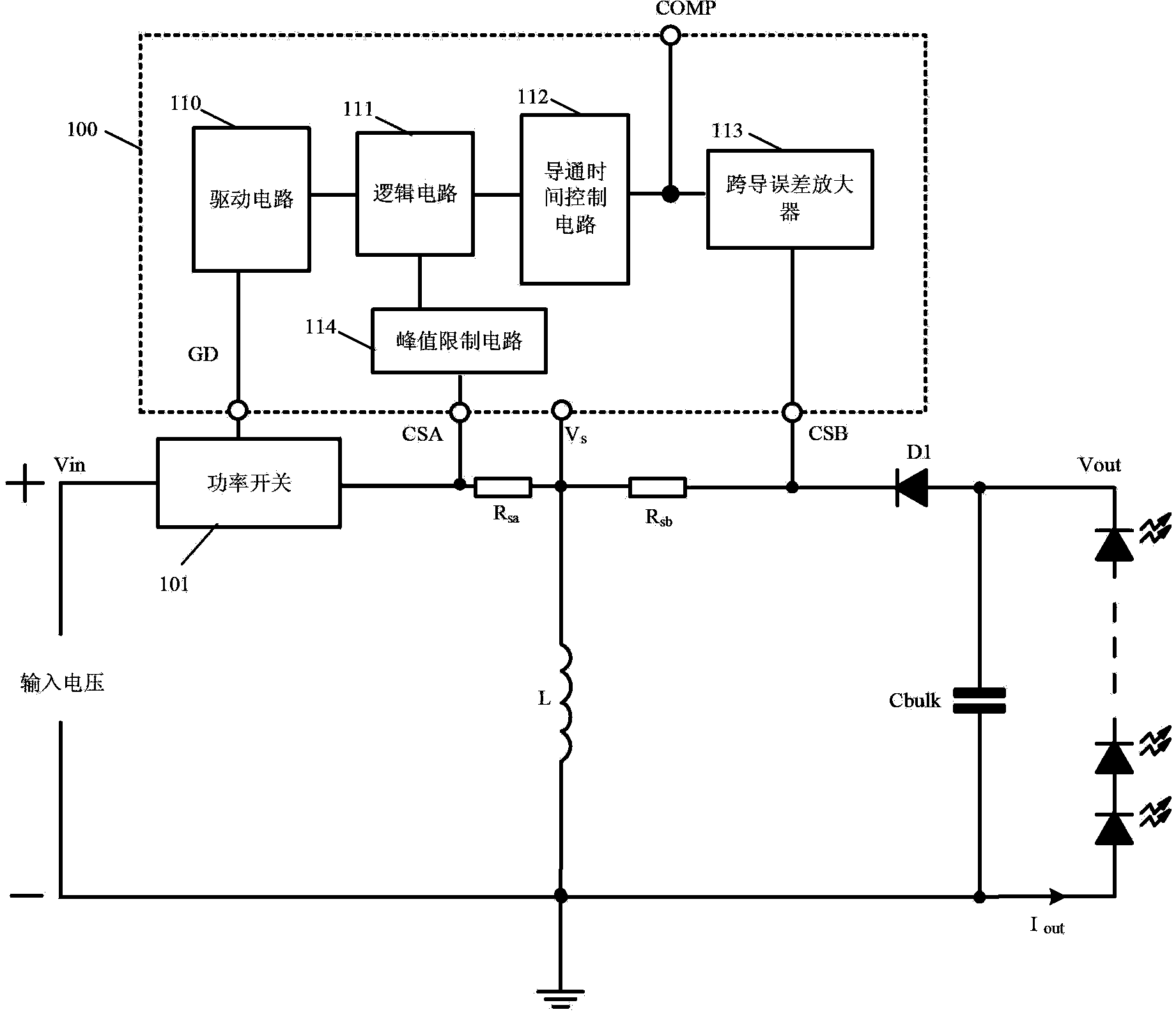
[0006] exist figure 1 shown in the circuit, respectively using the first sampling resistor R sb and the second sampling resistor R sa Sampling the output current and the current flowing through the power switch 101, although the circuit implementation is relatively simple, it needs to use two sampling resistors, and the controller 100 needs two pins CSA, CSB to be connected to the peripheral circuit, which is not conducive to further reducing the power consumption of the controller 100. the pin

Method used


Image

  • Buck-boost switching power supply and controller thereof
  • Buck-boost switching power supply and controller thereof
  • Buck-boost switching power supply and controller thereof

Examples


Embodiment Construction

[0037] The present invention will be further described below in conjunction with specific embodiments and accompanying drawings, but the protection scope of the present invention should not be limited thereby.

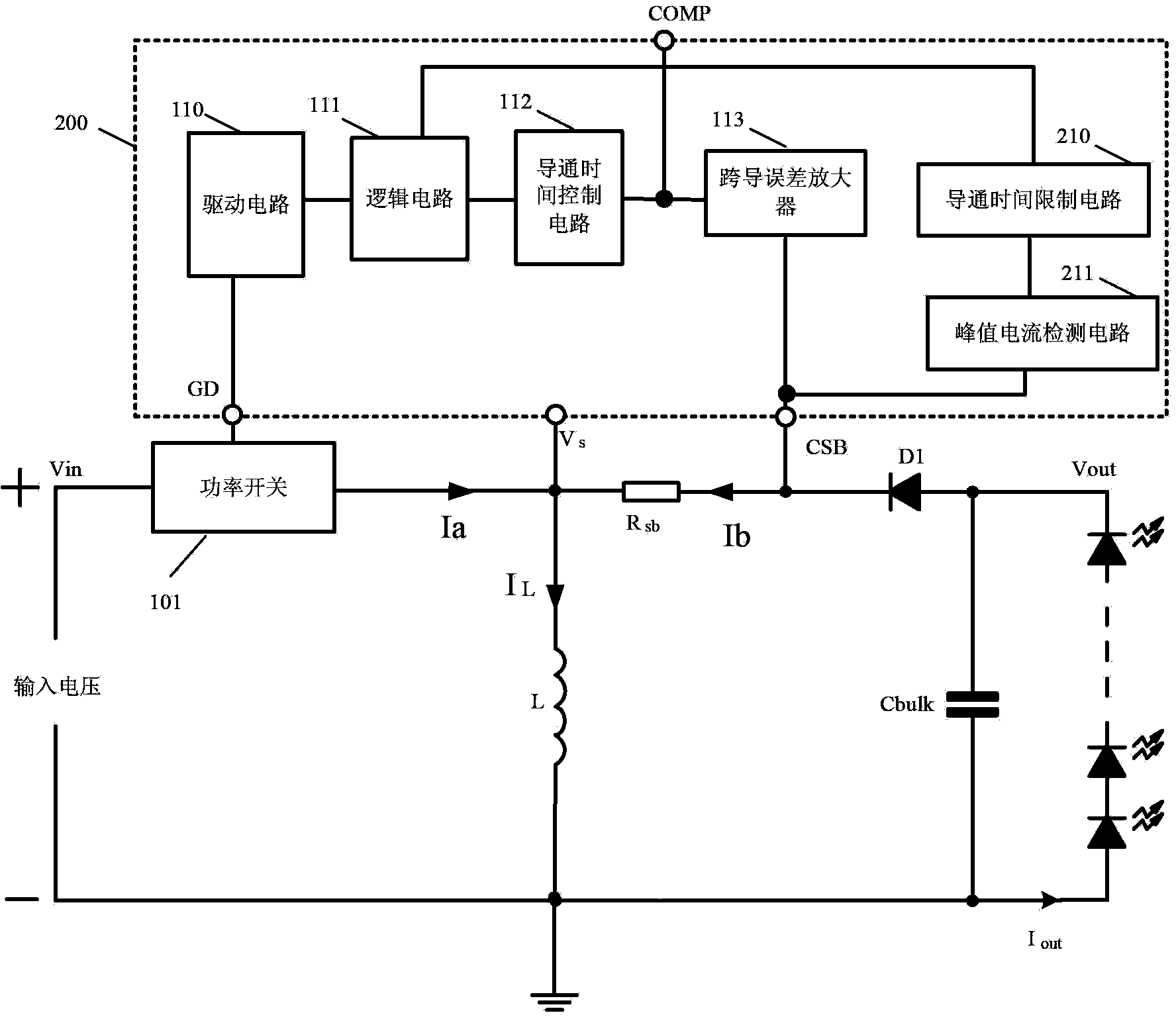
[0038] refer to figure 2 , the buck-boost switching power supply of this embodiment includes: a switching power supply controller 200, a power switch 101, an inductor L, a sampling resistor R sb , Freewheeling diode D1, output capacitor Cbulk.

[0039] Wherein, the first terminal of the power switch 101 receives the input voltage Vin, the control terminal of the power switch 101 receives the driving signal output by the switching power supply controller 200, and the driving signal is output through the port GD, and the second terminal of the power switch is connected to the second terminal of the inductor L. One end and the sampling resistor R sb the first end of . The port Vs connected to the second end of the power switch 101 also serves as the floating ground of...


PUM


Abstract

The invention provides a buck-boost switching power supply and a controller thereof. The controller comprises a transconductance error amplifier, an on time control circuit, a peak current detection circuit, an on time limit circuit and a logic circuit. An input end of the transconductance error amplifier receives externally input sample voltage and subjects the voltage with preset reference voltage to transconductance error amplification. An output end of the transconductance error amplifier is connected with a compensation port, and an external compensation capacitor is configured to the compensation port. The on time control circuit determines on-time of a power switch according to the voltage of the compensation port. The peak current detection circuit acquires the value of current flowing through the power switch in a previous power switching period according to the sample voltage. The on time limit circuit determines a maximum on-time limit of the power switch in one or a plurality of follow-up power switching periods according to signals output by the peak current detection circuit. The logic circuit generates drive signals to control on and off of the power switch according to the one-time and the maximum on-time limit. As the circuit structure is simplified, smaller package is available and cost can be lowered.

Description

technical field [0001] The invention relates to switching power supply technology, in particular to a buck-boost switching power supply and a controller thereof. Background technique [0002] refer to figure 1 , in the traditional LED drive circuit with buck-boost structure, when the power switch 101 is turned on, the input current flows through the power switch 101, the second sampling resistor R sa , inductor 103, the current on the inductor 103 increases, the inductor 103 stores energy, and the second sampling resistor R sa The current flowing through the power switch 101 is sampled to obtain a second sampled voltage. When the power switch 101 is turned off, the current flows through the inductor 103, the first sampling resistor R sb , the freewheeling diode D1, the output load capacitor Cbulk, and the LED light string, the current on the inductor 103 decreases, and the inductor 103 releases energy to the output load capacitor Cbulk and the LED light string. The first...

Claims


Application Information

Patent Timeline
Patent Type & Authority Patents(China)
IPC IPC(8): H02M3/10H02M1/32H02M1/00H03F3/45
Inventor 姚云龙吴建兴
Owner HANGZHOU SILAN MICROELECTRONICS
Learn More