A single-segment linear constant power LED drive circuit and method

A technology of LED driving and driving method, applied in the field of circuit design, can solve problems such as low efficiency and narrow input voltage range, achieve high efficiency, simplification of peripheral circuits, and achieve the effect of linear shutdown

Active Publication Date: 2019-06-21
CRM ICBG (WUXI) CO LTD
View PDF5 Cites 0 Cited by
  • Summary
  • Abstract
  • Description
  • Claims
  • Application Information

AI Technical Summary

Problems solved by technology

[0008] In view of the shortcomings of the prior art described above, the purpose of the present invention is to provide a single-segment linear constant power LED drive circuit and method for solving the problem of narrow input voltage range and low efficiency in single-segment linear LED drive in the prior art. question

Method used


Image

  • A single-segment linear constant power LED drive circuit and method
  • A single-segment linear constant power LED drive circuit and method
  • A single-segment linear constant power LED drive circuit and method

Examples


Embodiment 1

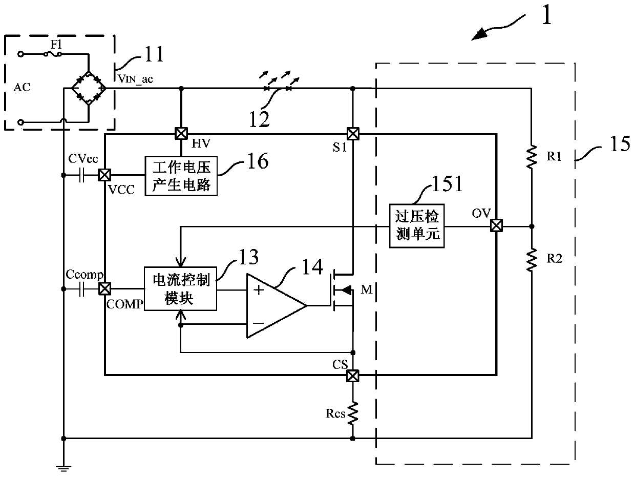
[0051] Such as figure 2 As shown, the present invention provides a single-segment linear constant power LED drive circuit 1, the single-segment linear constant power LED drive circuit 1 at least includes:

[0052] Voltage input module 11 , LED load 12 , power switch tube M, sampling resistor Rcs, current control module 13 , comparison module 14 , overvoltage control module 15 and working voltage generation circuit 16 .

[0053] Such as figure 2 As shown, the voltage input module 11 is used to provide the input voltage V IN _ac.

[0054] Specifically, such as figure 2 As shown, the voltage input module 11 is an external chip device, including an AC power supply AC, a fuse F1 and a rectification unit, the rectification unit includes two parallel diode groups, each diode group includes two diodes connected in series, The AC power supply AC is connected between two diodes of each diode group through the fuse F1, and the voltage input module 11 provides the input voltage V ...

Embodiment 2

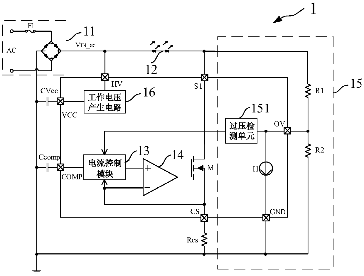
[0070] Such as image 3 As shown, the present invention provides a single-segment linear constant power LED drive circuit, the structure of which is basically the same as that of Embodiment 1, the difference is that the overvoltage control module 15 also includes a constant current source I1 to adjust the current flow through The turn-off slope of the current of the LED load 12 further reduces electromagnetic interference and optimizes circuit performance.

[0071] Specifically, such as image 3 As shown, the overvoltage control module 15 includes a first resistor R1 , a second resistor R2 , a constant current source I1 and an overvoltage detection unit 151 . In this embodiment, the first resistor R1 and the second resistor R2 are external devices on the chip, and the constant current source I1 and the overvoltage detection unit 151 are on-chip devices. One end of the first resistor R1 is connected to the drain terminal S1 of the power switch tube M, the other end is connect...


PUM


Abstract

The present invention provides a single-segment linear constant power LED drive circuit and method, comprising: a voltage input module; an LED load; a power switch tube; a sampling resistor; an overvoltage control module for detecting the drain terminal voltage of the power switch tube; limiting the peak current of the LED load The current control module; and the comparison module. When the input voltage is greater than the conduction voltage of the LED load, the current control module limits the peak current so that the average value of the current in different input voltage cycles is constant, and when the input voltage is greater than the set value, the LED that flows through the LED is turned off load current, thereby reducing power consumption; when the input voltage is lower than the conduction voltage of the LED load, the LED load is cut off. The invention realizes the control of the average current in the AC cycle by the compensation capacitor, limits the peak current, and realizes constant power output in a wide input voltage range; adjusts the turn-off voltage and turn-off slope of the LED through an external resistor to achieve high system efficiency and Optimize the EMI performance of the system.

Description

technical field [0001] The invention relates to the field of circuit design, in particular to a single-segment linear constant power LED driving circuit and method. Background technique [0002] LED is a semiconductor electronic component that can emit light. This electronic component can only emit red light with low luminosity in the early days. With the continuous advancement of technology, it has now developed to the extent that it can emit visible light, infrared rays and ultraviolet rays. Big improvement. LED has the advantages of high efficiency, long life, unbreakable, high switching speed, high reliability, etc. that traditional light sources cannot match, and has been widely used in the fields of indicator lights, displays and lighting. [0003] Usually, the overall efficiency of a single-segment linear LED driver is determined by the LED conduction voltage and the input voltage, which satisfy the following relationship: [0004] Such as figure 1 Shown is a com...

Claims


Application Information

Patent Timeline
Patent Type & Authority Patents(China)
IPC IPC(8): H05B33/08H05B44/00
CPCH05B45/395Y02B20/30H05B47/24H05B45/14
Inventor 刘军吴泉清李国成
Owner CRM ICBG (WUXI) CO LTD
Why Eureka
Try Eureka