Heating wire driving circuit and electronic equipment

A driving circuit and heating wire technology, which is applied in ohmic resistance heating circuit diagrams, electrical components, electric heating devices, etc., can solve problems such as high cost, low control cycle, and low precision of triangular wave generators, so as to improve output accuracy and avoid conduction Resistance, the effect of improving current accuracy and anti-interference ability

Active Publication Date: 2021-11-26
SHENZHEN LOWPOWER SEMICON CO LTD
View PDF0 Cites 0 Cited by
  • Summary
  • Abstract
  • Description
  • Claims
  • Application Information

AI Technical Summary

Problems solved by technology

[0008] The purpose of the present invention is to provide a heating wire driving circuit, aiming to solve the problem of low precision or high cost of the triangular wave generator caused by the low PWM control period in the traditional heating wire driving circuit

Method used


Image

  • Heating wire driving circuit and electronic equipment
  • Heating wire driving circuit and electronic equipment
  • Heating wire driving circuit and electronic equipment

Examples


Embodiment 1

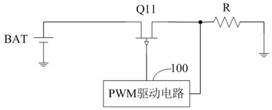
[0038] Such as image 3 as shown, image 3 The first structure schematic diagram of the heating wire driving circuit provided by the embodiment of the present invention, the heating wire driving circuit includes a battery BAT, a MOS transistor Q11 and a PWM driving circuit 100, the battery BAT, the MOS transistor Q11 and the heating wire R are connected in sequence, and the PWM drives The circuit 100 is connected to the gate and the output terminal of the MOS transistor Q11 respectively.

[0039]Wherein, the power terminal of the battery BAT is connected to the input terminal of the MOS transistor Q11 to provide driving power, the PWM driving circuit 100 obtains the terminal voltage of the heating wire R and converts and outputs the PWM signal to the MOS transistor Q11, and the MOS transistor Q11 corresponds to the PWM signal Turn on, and convert and output the required voltage and current to the heating wire R to achieve constant power output. The PWM drive circuit 100 perfo...


PUM


Abstract

The present invention proposes a heating wire driving circuit and electronic equipment, wherein the heating wire driving circuit includes a battery, a MOS tube and a PWM driving circuit, and the PWM driving circuit includes a first triangular wave generating circuit, a second triangular wave generating circuit, a counting circuit and a PWM output Circuit, the frequency of the first triangular wave pulse signal and the frequency of the second triangular wave pulse signal are N times of the PWM signal, therefore, a larger current source can be designed inside the triangular wave generator, or a smaller capacitor can be designed inside the triangular wave generator, In order to improve the current accuracy and anti-interference ability, or reduce the area or cost of the triangular wave generator, at the same time, the duty cycle of the generated PWM signal is the ratio of the square of the target RMS voltage to the square of the terminal voltage of the heating wire, so as to improve the output Accuracy and the purpose of achieving constant power output.

Description

technical field [0001] The invention belongs to the technical field of electronic circuits, and in particular relates to a heating wire driving circuit and electronic equipment. Background technique [0002] Many electronic devices need heating control. The heating method is to output a voltage to the heating wire, and the heating power is controlled by the voltage supplied to the heating wire. For example, the smoke of electronic cigarettes needs to be discharged to the heating wire through the battery to provide power, and the heating wire heats the atomizer to generate smoke. [0003] Among them, the power of the heating wire is the root mean square value of the voltage at both ends of the heating wire (the root mean square value will be referred to as RMS value in the following) divided by the resistance value of the heating wire. For power supply, the voltage of the battery gradually decreases with the discharge process. In order to keep the output power constant, the ...

Claims


Application Information

Patent Timeline
Patent Type & Authority Patents(China)
IPC IPC(8): H02M7/53
CPCH05B3/0019H05B3/0023H05B1/02
Inventor 赖哲人戴兴科沈再雄丛峰陈超
Owner SHENZHEN LOWPOWER SEMICON CO LTD
Why Eureka
Try Eureka