
LED drive circuit and LED power supply

A technology of LED driving and driving power, applied in electrical components and other directions, can solve the problems of increased cost and high difficulty of circuit development

Pending Publication Date: 2021-03-05
LEEDARSON IOT TECH INC
View PDF0 Cites 0 Cited by
  • Summary
  • Abstract
  • Description
  • Claims
  • Application Information

AI Technical Summary

Problems solved by technology

[0005] The purpose of the present invention is to provide an LED drive circuit and LED power supply, aiming to solve the problems of high difficulty in circuit development and increased cost in the traditional constant power drive technical solutions

Method used


Image

  • LED drive circuit and LED power supply
  • LED drive circuit and LED power supply
  • LED drive circuit and LED power supply

Examples


Embodiment Construction

[0038] In order to make the object, technical solution and advantages of the present invention clearer, the present invention will be further described in detail below in conjunction with the accompanying drawings and embodiments. It should be understood that the specific embodiments described here are only used to explain the present invention, not to limit the present invention.

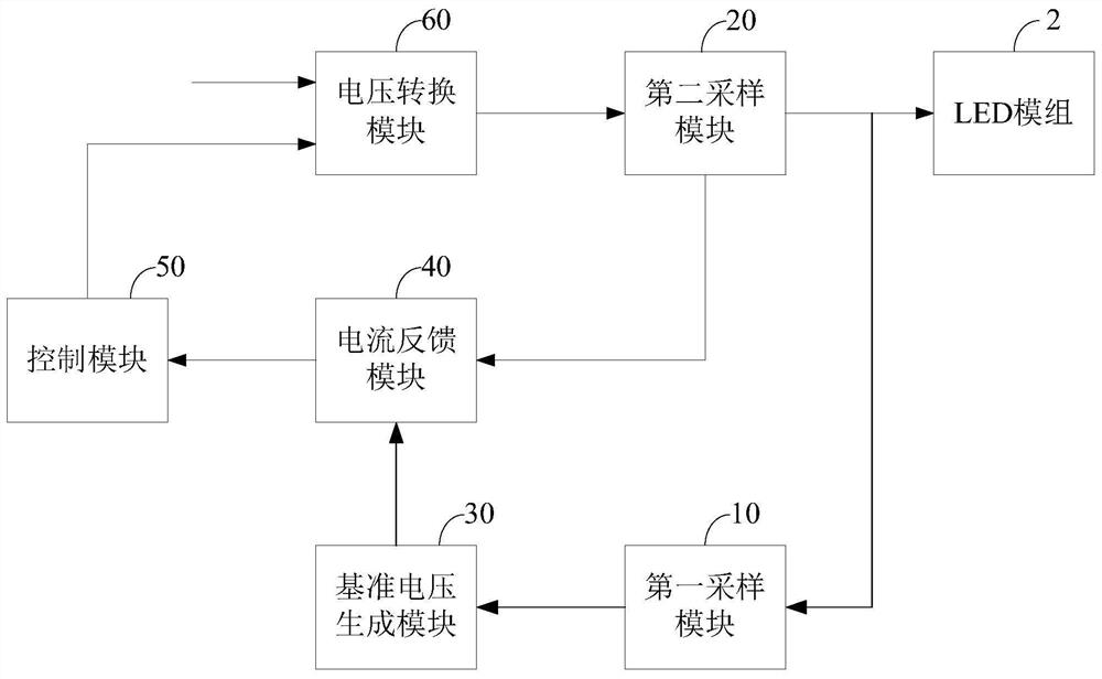
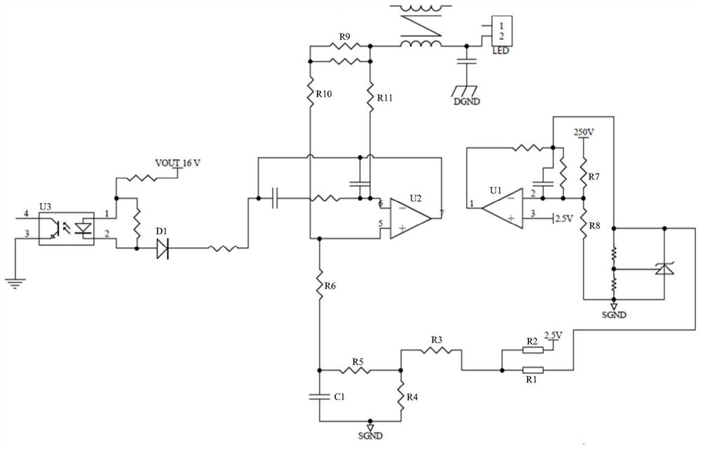
[0039] figure 1 A schematic structural diagram of the LED driving circuit provided by the embodiment of the present invention is shown. Such as figure 1 As shown, the LED driving circuit is connected to the LED module 2 , and the LED driving circuit includes: a first sampling module 10 , a second sampling module 20 , a reference voltage generation module 30 , a feedback module 40 , a control module 50 and a voltage conversion module 60 . The first sampling module 10 is used to generate a voltage sampling signal according to the driving power supply; the second sampling module 20 is used to genera...


PUM


Abstract

The invention belongs to the technical field of power supplies, and provides an LED drive circuit and an LED power supply. The LED drive circuit is connected with an LED module and comprises a first sampling module, a second sampling module, a reference voltage generation module, a feedback module, a control module and a voltage conversion module. The first sampling module is used for generating voltage sampling signals according to the driving power supply; the second sampling module is used for generating a current sampling signal according to the driving power supply; the reference voltagegeneration module is used for generating a first reference voltage according to the voltage sampling signal; the feedback module is used for generating a feedback signal according to the first reference voltage and the current sampling signal; the control module is used for generating a control signal according to the feedback signal; and the voltage conversion module is used for converting an input voltage into a driving power supply according to the control signal so as to drive the LED module.

Description

technical field [0001] The invention belongs to the technical field of power supplies, and in particular relates to an LED driving circuit and an LED power supply. Background technique [0002] The forward voltage (Forward Voltage, VF) of different LED light sources is quite different, and the VF of different batches or different manufacturers of the same combination of LED light sources will also have great deviations. Therefore, when using an ordinary constant current power supply, the input power of the same batch of LED lights will vary greatly; the VF of the LEDs will have greater differences under different combinations of LED light sources connected in series or in parallel. It is necessary to use power supply products of various current specifications to meet the demand, which requires customers to prepare power supplies of various specifications, resulting in increased costs; there are also difficulties in selecting power supplies, and it is necessary for profession...

Claims


Application Information

Patent Timeline
IPC IPC(8): H05B45/3725H05B45/30
Inventor 周辉志
Owner LEEDARSON IOT TECH INC
Learn More