Wire Cutting Power Control System

A technology of power supply control and wire cutting, which is applied to circuits, manufacturing tools, electric processing equipment, etc., can solve problems such as unfavorable and stable cutting processing, power supply energy waste, and power tube temperature rise, so as to improve the cutting quality of workpieces and reduce heat. Produces the effect of constant pulse width

Active Publication Date: 2019-04-02
泰州龙芯微电子技术有限公司
View PDF7 Cites 0 Cited by
  • Summary
  • Abstract
  • Description
  • Claims
  • Application Information

AI Technical Summary

Problems solved by technology

There are many ways to deal with current limiting, the simplest is to use resistors to limit current in the power stage; there are also pulse modulation and cycle control to control multiple power tubes in the linear region to achieve current limiting; the power stage adopts resistor current limiting, making a large number of power supplies Energy is wasted on resistance heating, which is not conducive to stable cutting process, low cutting efficiency, and high molybdenum wire loss. The pulse digital signal is used to control the power tube to work in the linear area. Since the linear area of ​​the power tube is small, the output The cutting pulse width is small, so it is difficult to work effectively when cutting large thickness workpieces; at the same time, because the output current is controlled by the input signal, when the current required for cutting (the current determined by the internal resistance of the ionization channel) is greater than the output current When , the voltage waveform will be distorted, resulting in the deviation of the surface quality of the cut workpiece
When the power supply is short-circuited, although the output current is controlled, since all the voltage is applied to the power tube, the power tube will be saturated instantly, which will easily damage the power tube or cause the temperature of the power tube to rise rapidly.

Method used


Image

  • Wire Cutting Power Control System
  • Wire Cutting Power Control System
  • Wire Cutting Power Control System

Examples


Embodiment Construction

[0017]The following will clearly and completely describe the technical solutions in the embodiments of the present invention with reference to the accompanying drawings in the embodiments of the present invention. Obviously, the described embodiments are only some, not all, embodiments of the present invention. Based on the embodiments of the present invention, all other embodiments obtained by persons of ordinary skill in the art without making creative efforts belong to the protection scope of the present invention.

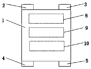
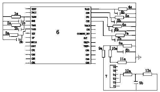
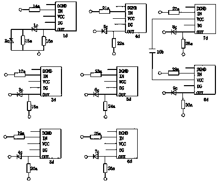
[0018] see Figure 1-4 , the present invention provides a technical solution: a wire cutting power supply control method, the control method mainly includes the following steps:

[0019] A. Set the parameters of high-frequency oscillation on the control panel of the cutting machine, and output high-frequency oscillation waves;

[0020] B. The high-frequency oscillating wave is amplified through the power amplification module in the control power supply body, a...


PUM


Abstract

The invention discloses a linear cutting power control method and system. The control method mainly comprises the following steps that A, a high-frequency oscillation parameter is set on a cutting machine control panel, and a high-frequency oscillation wave is output; B, the high-frequency oscillation wave is subjected to power amplification through a power amplification module in a control power body and used for discharged cutting; C, a cutting voltage and a cutting current in the cutting process are measured in real time through a current / voltage sampling module in the control power body; D, collected voltage data and collected current data are obtained through a current analysis module, butterfly transformation is conducted with 64 points as a cycle, and the no-load component, the discharge component and the short circuit component in voltage waveforms and current waveforms are analyzed; and E, a constant current is output through a high-frequency power output port. According to the linear cutting power control method and system, the control precision is high, low-voltage cutting can be achieved, and meanwhile, the constant current can be output unimpededly, so that the effectiveness is achieved, and the power energy utilization rate is increased.

Description

technical field [0001] The invention relates to the technical field of power supplies for cutting machines, in particular to a wire cutting power supply control system. Background technique [0002] In order to avoid the workpiece and molybdenum wire arcing, the existing wire cutting power supply adopts high voltage processing (DC 80-120V); in order to prevent the high frequency pulse current from being too large, it is necessary to use resistance current limiting at the power pole or use coil inductance or capacitor group for energy storage , the prior art includes high frequency oscillation and current limiting processing. High-frequency oscillation generates high-frequency pulses for cutting, and the current limiting treatment is to prevent excessive current from burning molybdenum wire and other electronic components. There are many ways to deal with current limiting, the simplest is to use resistors to limit current in the power stage; there are also pulse modulation a...

Claims


Application Information

Patent Timeline
Patent Type & Authority Patents(China)
IPC IPC(8): B23H7/04B23H7/14
CPCB23H7/04B23H7/20
Inventor 戴祥
Owner 泰州龙芯微电子技术有限公司
Why Eureka
Try Eureka