
Tire inflation system with discrete deflation circuit

一种充气系统、气动回路的技术,应用在轮胎测量、重型轮胎、轮胎零部件等方向,能够解决不能够响应轮胎压力、降低轮胎性能、降低轮胎寿命等问题

Active Publication Date: 2013-04-03
HENDRICKSON USA L L C
View PDF7 Cites 18 Cited by
  • Summary
  • Abstract
  • Description
  • Claims
  • Application Information

AI Technical Summary

Problems solved by technology

More specifically, in the absence of deflated-capable wheel valves, this prior art system is unable to respond to excessively increased tire pressure due to increased ambient air temperature, as noted above for non-deflated prior art systems. described
Accordingly, such prior art tire inflation systems may cause the tire to operate under conditions of significant overinflation, which undesirably reduces tire performance and, in turn, reduces tire life.

Method used


Image

  • Tire inflation system with discrete deflation circuit
  • Tire inflation system with discrete deflation circuit
  • Tire inflation system with discrete deflation circuit

Examples


Embodiment Construction

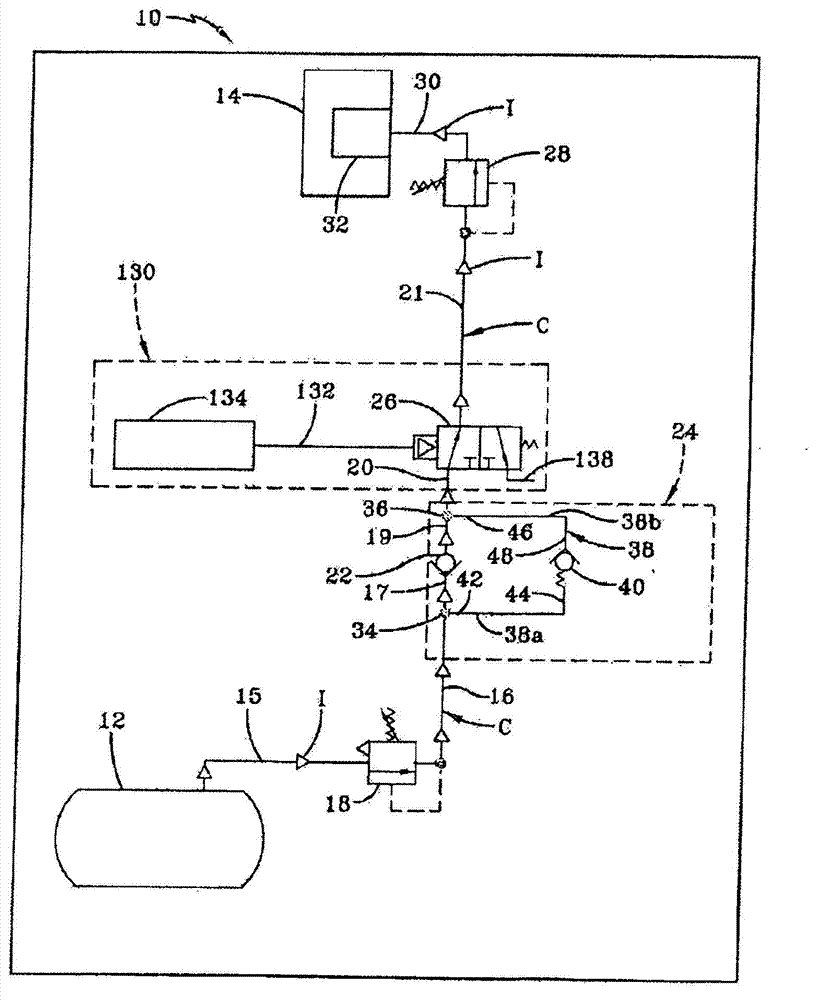
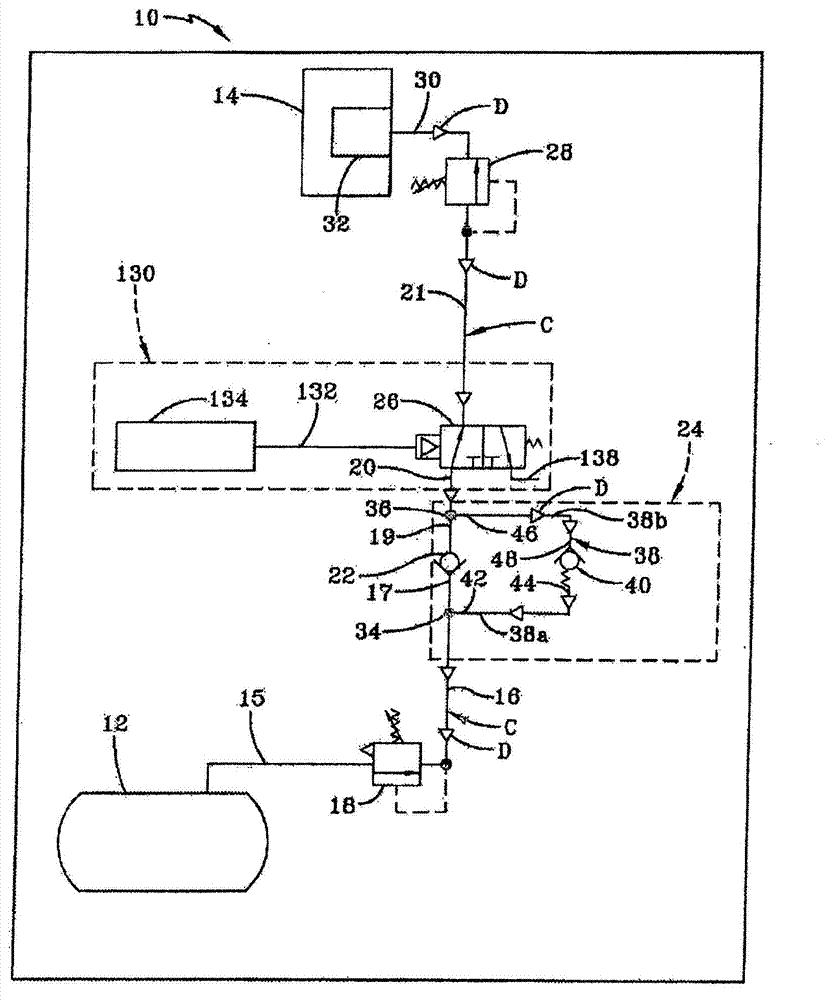
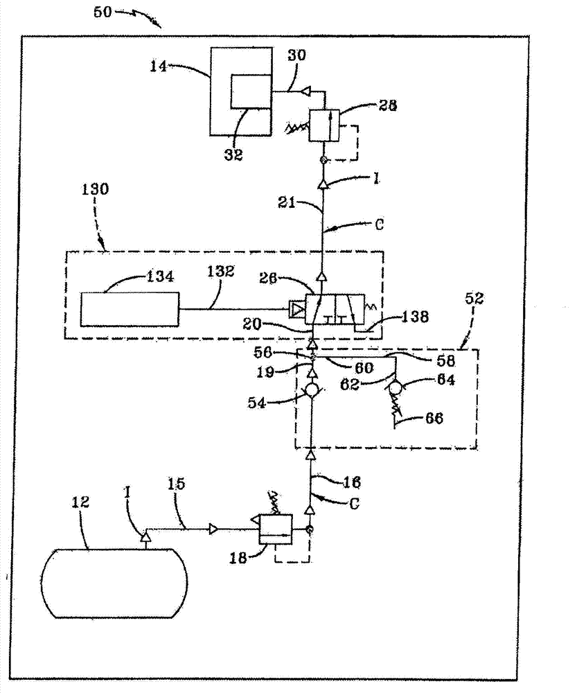
[0043] The present invention relates to a tire inflation system comprising a deflation circuit separate or separate from an inflation circuit. A separate deflation circuit is capable of controlling deflation of the tire according to specific predetermined conditions, which will be described in the exemplary embodiment of the present invention. Use these specific predetermined conditions to prevent the deflation of the tires until the vehicle is stopped, or to limit the amount of deflation of the tires, thereby preventing the tire pressure from dropping below a minimum predetermined pressure, such as set by NHTSA and / or the tire manufacturer for a specific vehicle The minimum recommended pressure for the load. It should be understood that the term target pressure referred to hereinafter refers to a desired target inflation pressure selected by the vehicle operator based on the cold inflation pressure or cold pressure of the vehicle tires.

[0044] now go to Figure 1A , a firs...


PUM


Abstract

A vehicle tire inflation system includes an air supply source in fluid communication with multiple tires of the vehicle. A pneumatic conduit extends between and is in fluid communication with the air supply source and the tires. Means are fluidly connected to the pneumatic conduit for enabling selective inflation and deflation of the tires. The means include a first pneumatic circuit for inflation of the tires, and a second pneumatic circuit for deflation of the tires. The second pneumatic circuit is discrete from the first pneumatic circuit and is common to more than one of the tires. The means provides controlled deflation of the tires in the second pneumatic circuit based upon a predetermined condition, preventing deflation of the tires until the vehicle is parked, or limiting the deflation of the tires, which in turn enables the tire inflation system to accommodate a desirable increased pressure in the tires.

Description

[0001] Cross references to related patent applications [0002] This application claims priority to US Provisional Patent Application Serial No. 61 / 369,159, filed July 30, 2010. technical field [0003] The present invention relates to the field of tire inflation systems. More specifically, the present invention relates to tire inflation systems for heavy duty vehicles, such as trucks and tractor-trailers or semi-trailers, that are capable of being operated while the vehicle is in motion. More particularly, the present invention relates to tire inflation systems that include a tire deflation circuit that is separate or separate from the inflation circuit so that tire deflation can be controlled based on specific predetermined conditions. Background technique [0004] Heavy-duty vehicles typically include trucks and tractor-trailers or semi-trailers. Tractor-trailers and semi-trailers (collectively called tractor-trailers for convenience) consist of at least one trailer, an...

Claims


Application Information

Patent Timeline
Patent Type & Authority Applications(China)
IPC IPC(8): B60C23/10
CPCB60C23/003B60C23/00B60C23/10B60C2200/06B60C23/00354B60C23/00372
Inventor M·威尔逊J·塞万提斯S·帕杜拉
Owner HENDRICKSON USA L L C
Learn More