
Automobile braking energy recovery and active auxiliary braking automatic control system

A braking energy recovery and automatic control system technology, applied in the direction of brakes, braking components, automatic starting devices, etc., can solve the problems that cannot quickly convert and absorb a large amount of energy, cannot reflect advantages, and the fuel-saving effect is not obvious, etc., to achieve large Reliability and environmental adaptability, protection of life and property safety, significant effect on social value

Inactive Publication Date: 2013-03-20
ZHONGBEI UNIV
View PDF4 Cites 13 Cited by
  • Summary
  • Abstract
  • Description
  • Claims
  • Application Information

AI Technical Summary

Problems solved by technology

[0004] (1) Mechanical energy storage, such as flywheel energy storage, has a relatively low energy density because it relies on rotational inertia to store part of the energy, and the cost of ensuring system safety is high. Its advantages cannot be realized in small-scale occasions, and the technology is difficult. Fuel-saving effect is not obvious;
[0005] (2) Hydraulic energy storage, once a failure occurs in this way, it is not easy to discharge, especially when leakage occurs, it will pollute the environment and the cost is also expensive;
[0006] (3) Battery energy storage has good performance in all aspects, but the power density is low, the charging and discharging frequency is small, and it cannot quickly convert and absorb a large amount of energy. When the vehicle brakes or starts, it needs to release or obtain a large amount of energy quickly. This greatly limits the application of energy storage batteries

Method used

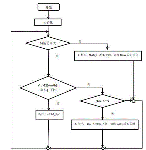

Image

  • Automobile braking energy recovery and active auxiliary braking automatic control system
  • Automobile braking energy recovery and active auxiliary braking automatic control system

Examples


Embodiment Construction

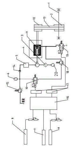
[0026] The invention will be further described below in conjunction with the accompanying drawings.

[0027] Such as figure 1 Shown, the present invention mainly comprises:

[0028] The transmission mechanism includes a pulley set and a pneumatic clutch 11. The pulley set includes a large pulley 2, a small pulley 12 and a belt 13. The large pulley 2 is mounted on the automobile half shaft 1 and is connected to the small pulley 12 through the belt 13. The small pulley 12 is connected to the Pneumatic clutch 11 is mechanically connected;

[0029] The pneumatic circuit device includes an air compressor 4, a control valve, an air storage tank 6 and an air treatment device 5, the control valve includes a solenoid valve 10 and a pressure reducing valve 18, and the power input end of the air compressor 4 is mechanically connected with a pneumatic clutch 11, The exhaust port of the air compressor is connected to the air treatment device 5, the air inlet of the air compressor is ...


PUM


Abstract

The invention provides an automobile braking energy recovery and active auxiliary braking automatic control system, mainly comprising a transmission mechanism, a pneumatic circuit device and an electrical control group, wherein the transmission mechanism comprises a belt wheel group and a pneumatic clutch; the pneumatic circuit device comprises an air compressor, a control valve, an air storage tank and an air processing device; and the electrical control group comprises an electrical control unit and a sensor. According to the invention, with adoption of pneumatic energy storage, the requirements on two aspects, namely braking energy recovery and active auxiliary braking, are both taken into consideration, when a vehicle goes downhill for a long distance, an energy recovery and active auxiliary braking process can be started automatically, and the service life of the original braking device is prolonged; and in addition, when the vehicle is detected to be overspeed, an auxiliary braking process can be started automatically, so that the vehicle speed is reduced to a certain degree so as to facilitate the protection of life and property safety of a driver. The automobile braking energy recovery and active auxiliary braking automatic control system disclosed by the invention is low in cost and high in efficiency and safety, meets the requirement on energy saving and emission reduction and the requirement of modern vehicle design on high safety, and has obvious economic and social significance.

Description

technical field [0001] The invention relates to the field of automobile braking energy recovery and auxiliary braking, in particular to an automatic control system for vehicle braking energy recovery and active auxiliary braking. Background technique [0002] At present, due to the consideration of convenient transportation, more and more roads are built on different terrains, and mountainous expressways are affected by various factors such as terrain, topography, and road engineering economic costs. In the linear design, it is inevitable There will be road sections with steep slopes and long road sections, which are likely to cause vehicles to brake for a long time, brake continuously or slide in neutral. When a car passes through this type of ramp, it needs to overcome the potential energy of gravity to do work when going uphill, but it needs to decelerate through frequent braking actions when going downhill, so that kinetic energy is converted into heat energy and...

Claims


Application Information

Patent Timeline
IPC IPC(8): B60T1/10B60T7/12
Inventor 李晓杰岳喜凯苏铁熊张翼董小瑞
Owner ZHONGBEI UNIV
Learn More