Pneumatic circuit for tire testing device, tire testing device, and tire testing method

a pneumatic circuit and tire testing technology, applied in vehicle tyre testing, roads, instruments, etc., can solve the problems of affecting the measurement, reducing or increasing air pressure, and affecting the measurement, so as to improve the accuracy of tire inspection and short time , the effect of reducing the cos

Active Publication Date: 2012-04-12
KOBE STEEL LTD
View PDF12 Cites 13 Cited by
  • Summary
  • Abstract
  • Description
  • Claims
  • Application Information

AI Technical Summary

Benefits of technology

[0014]The present invention has an object to provide a pneumatic circuit for tire testing device, capable of surely adjusting minor variation of air pressure, which is caused during tire testing, in

Problems solved by technology

In the above-mentioned tire testing, the variation of the air pressure inside the tire during testing is known to seriously affect a measurement result of uniformity.
However, actual tire testing frequently involves change of air pressure, and the air pressure decreases or increases in rare cases.
However, even a change of air pressure as small as about 0.5 kPa seriously affects the measurement result of uniformity.
For example, when the repetitive stability of the testing device is confirmed, a same tire has to be repetitively tested.
However, if the air pressure inside the tire changes in

Method used


Image

  • Pneumatic circuit for tire testing device, tire testing device, and tire testing method
  • Pneumatic circuit for tire testing device, tire testing device, and tire testing method
  • Pneumatic circuit for tire testing device, tire testing device, and tire testing method

Examples


first embodiment

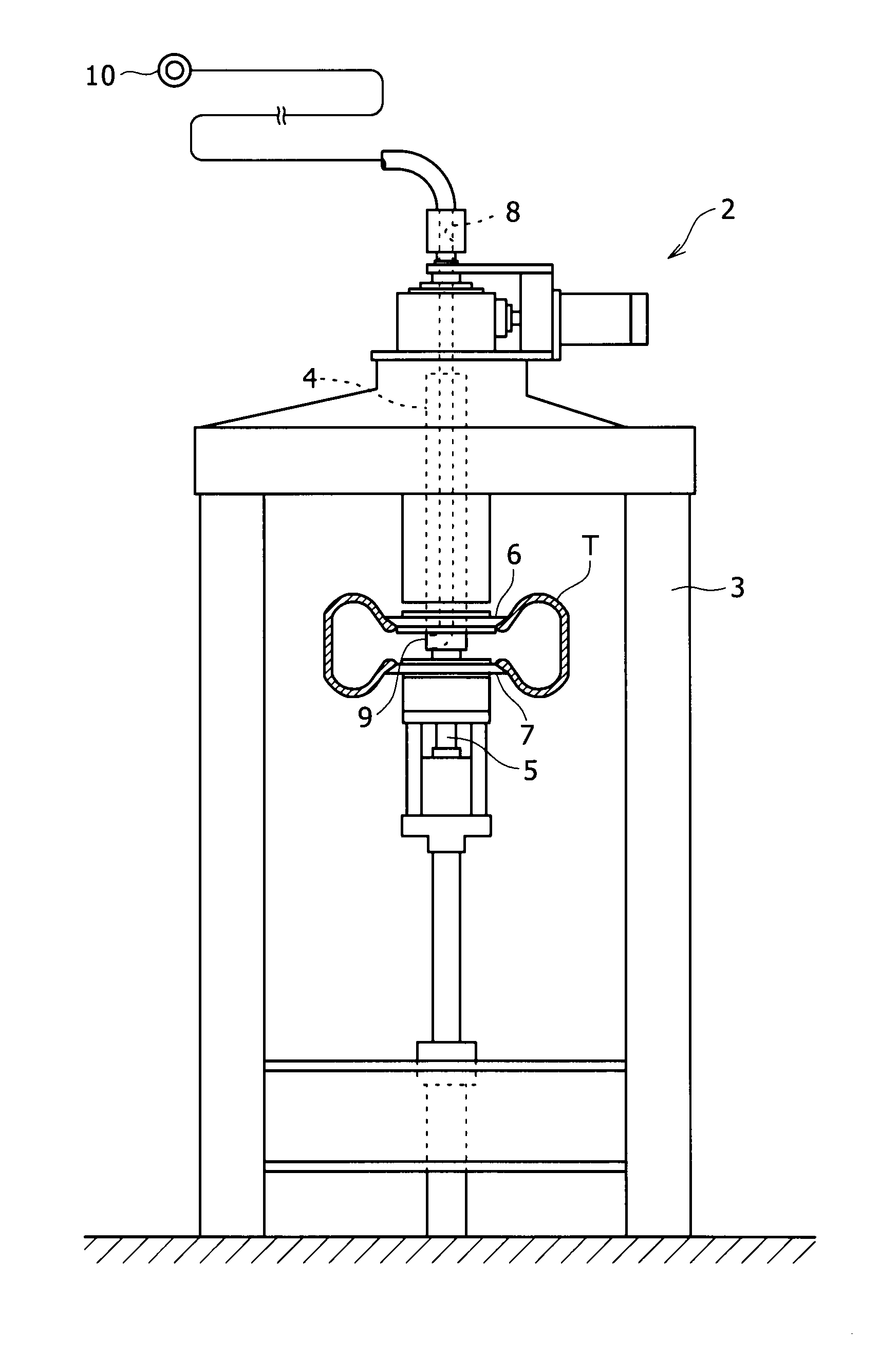
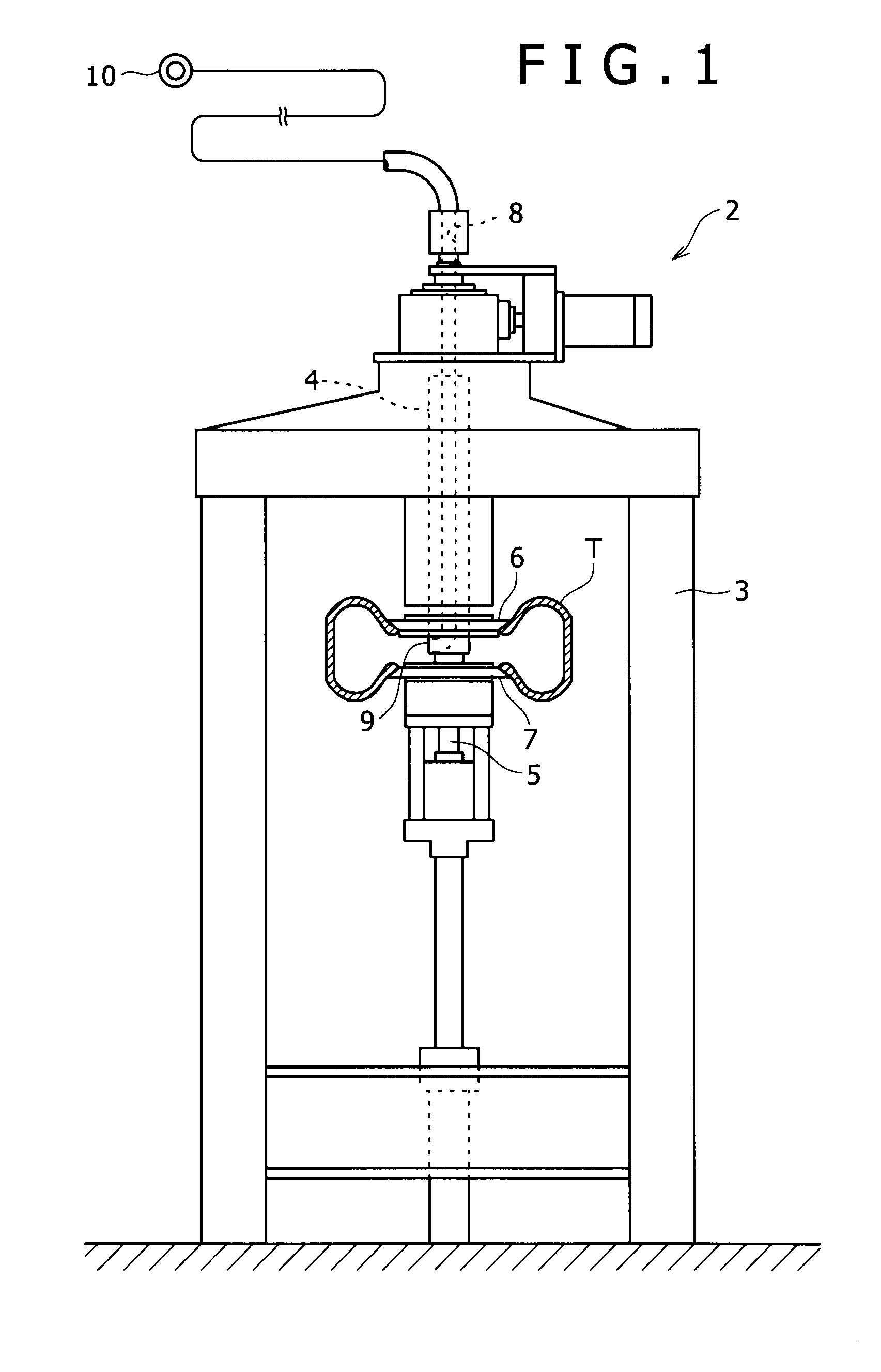
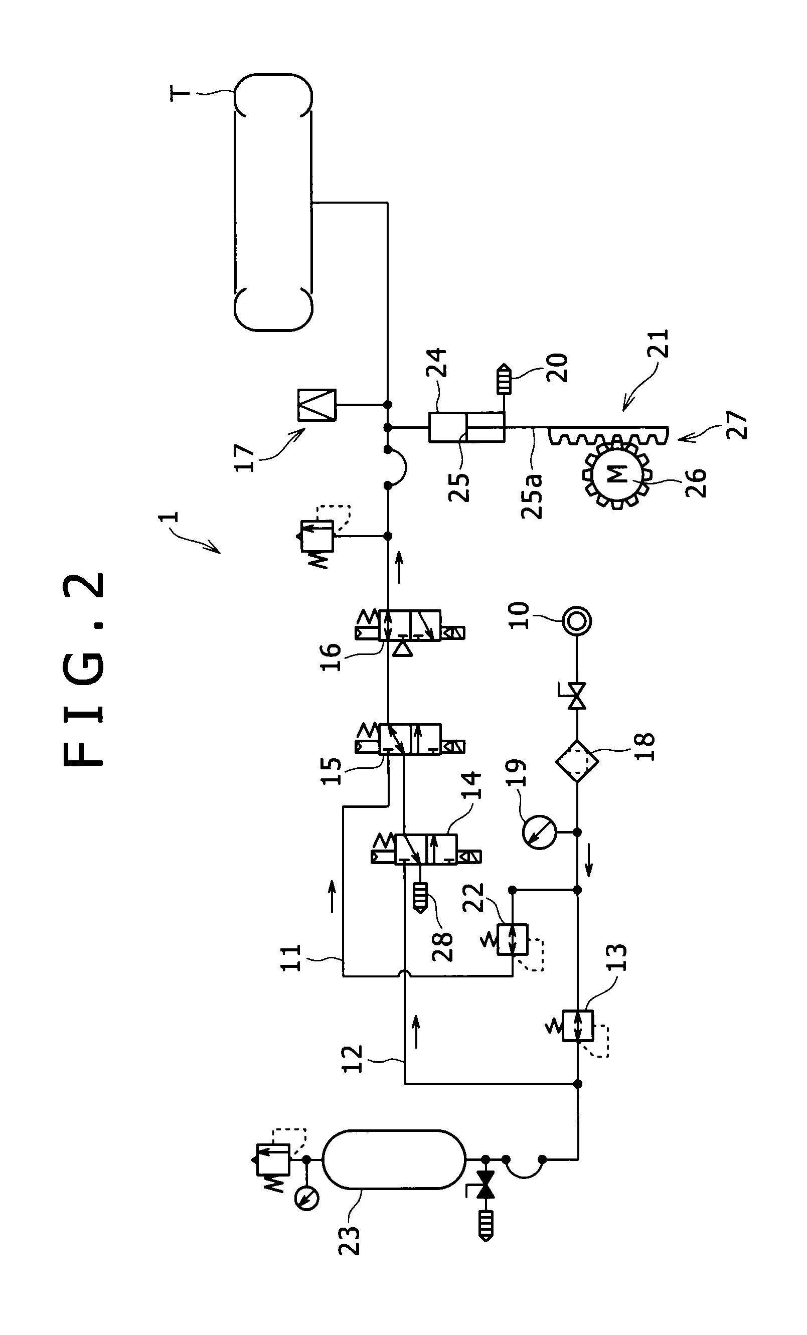
[0021]A pneumatic circuit 1 of the present invention and a tire testing device 2 provided with the pneumatic circuit 1 will be described based on FIGS. 1 and 2.

[0022]The tire testing device 2 is for performing a product inspection such as uniformity for a tire T as a finished product and is composed of a uniformity machine in this embodiment. The tire testing device 2 includes, as schematically shown in FIG. 1, a frame 3 provided on a floor surface in a tower shape; an upper tire shaft 4 and a lower tire shaft 5 mounted on the frame 3; rims 6, 7 fixed respectively to the tire shafts 4, 5; and a drum not shown. The tire shafts 4, 5 are disposed on upper and lower sides so as to be rotatable about a vertically extending common central axis. The rims 6, 7 are provided respectively on the lower end of the upper tire shaft 4 and on the upper end of the lower tire shaft 5, and the tire T is fixed to these rims 6, 7. The drum has an outer circumferential surface constituting a simulated ro...

second embodiment

[0058]Next, a pneumatic circuit 1 according to the present invention and a tire testing device 2 provided with the same will be described with reference to FIG. 3.

[0059]The pneumatic circuit 1 according to the second embodiment is differed from that of the first embodiment in the following points.

[0060]1) The positions of the supply / discharge valve 14 and the shutoff valve 16 are mutually replaced. Concretely, the supply / discharge valve 14 according to the second embodiment is provided in the flow path on the downstream side of the changeover valve 15, that is, in the airflow path between the shutoff valve 15 and the tire T installed between the rims 6, 7. The shutoff valve 16 according to the second embodiment is provided in the flow path of the testing system 12 that is the flow path on the upstream side of the changeover valve 15, and interposed between the changeover valve 15 and the pressure regulating valve 13.

[0061]2) The tank 23 and volume adjustment mechanism 21 according t...

third embodiment

[0066]A pneumatic circuit 1 according to the present invention and a tire testing device 2 provided with the same will be then described with reference to FIG. 4.

[0067]The pneumatic circuit 1 according to the third embodiment is not provided with the shutoff valve 16, unlike the second embodiment, although the tank 23 and the volume adjustment mechanism 21 are provided between the pressure regulating valve 13 and the supply / discharge valve 14 similarly to the second embodiment. A supply / discharge valve 29 is provided between the tank 23 and the volume adjustment mechanism 21. This supply / discharge valve 29 plays a part of the function (discharge of air in decompression from the bead seat pressure to the testing air pressure and discharge of air in release of the tire internal pressure after testing) of the supply / discharge valve 14 provided in the test system 12 of FIG. 2, and is used for the discharge of air in the decompression from the bead seat pressure to the testing air pressu...


PUM


Abstract

A pneumatic circuit whereby small amounts of variations in pneumatic pressure in a tire occurring during tire testing can be adjusted in a short time. The pneumatic circuit includes an air supply source which generates compressed air to be supplied to a tire retained in a tire testing device; a pressure regulating valve which regulates the pressure of the compressed air generated; a discharge/supply valve provided downstream of the pressure regulating valve and by which compressed air is supplied to, or discharged from, the tire; a pressure detection unit provided downstream of the discharge/supply valve and which detects the tire pressure inside the tire; and a volume adjustment mechanism provided between the pressure regulating valve and the tire and which increases or decreases the volume of compressed air in an airflow path between the tire and the pressure regulating valve, as well as in the tire.

Description

TECHNICAL FIELD[0001]The present invention relates to a pneumatic circuit used in a tire testing device such as a uniformity machine, a tire testing device provided with the pneumatic circuit, and a tire testing method for testing a tire by use of the pneumatic circuit.BACKGROUND ART[0002]Conventionally, a tire as a finished product is subjected to tire testing to determine the quality thereof by measuring uniformity or the like (uniformity check). For example, testing for uniformity measurement on a tire for passenger car is basically performed according to the following procedure by use of a testing device shown in Patent Literature 1.[0003]A tire testing device described in Patent Literature 1 includes a pair of upper and lower rims, a factory air source that outputs compressed air to be supplied to a tire held between both the rims, and a pneumatic circuit that regulates the pressure of the compressed air output from the factory air source and then supplies the resulting compres...

Claims


Application Information

Patent Timeline
IPC IPC(8): G01M17/02F16K15/20
CPCG01M17/021Y10T137/36
Inventor MURAKAMI, MASAOMATSUBARA, YOSHIAKINAKAYAMA, MAIKOTAKEDA, HAJIME
Owner KOBE STEEL LTD
Why Eureka
Try Eureka