Magnetic core type laminated inductor

a laminated inductor and magnetic core technology, applied in the direction of transformer/inductance details, inductance, inorganic material magnetism, etc., can solve the problems of inductors with thin profiles, inability to achieve downsizing, and rapid drop of inductance, so as to facilitate correct measurement and inspection, the effect of favorable direct-current superposition

Inactive Publication Date: 2006-07-13
AZ ELECTRONICS MATERIALS USA CORP +1
View PDF2 Cites 21 Cited by
  • Summary
  • Abstract
  • Description
  • Claims
  • Application Information

AI Technical Summary

Benefits of technology

[0020] An object of the present invention is to provide a magnetic core type laminated inductor which is capable of ensuring a large rated current that can assure an inductance value equal to or above a given level, of obtaining a favorable characteristic of relatively gentle variation of inductance in the entire current region within a rated range and thereby obtaining a favorable direct-current superposition characteristic, and moreover, of allowing correct measurement and inspection at a small current.

Problems solved by technology

Therefore, it has been difficult to achieve downsizing, or more particularly, to achieve thinner profiles of the inductors as compared to electronic components such as semiconductor integrated circuits.
However, the inductor has a problem that the inductance rapidly drops even at a small coil current (an exciting current) due to magnetic saturation of the magnetic bodies 30.
In other words, the inductor has a problem that it is not possible to achieve a sufficient rated current as a transformer or a choke coil because of a small current upper limit that can assure the inductance equal to or above a given level.
However, the following problems are found out.
However, the inductance is distinctively high in a region where the coil current is small, and the variation attributable to the coil current is steep and the characteristic is not stable.
Accordingly, there is also a problem of incapability to carry out correct inspection.

Method used


Image

  • Magnetic core type laminated inductor
  • Magnetic core type laminated inductor
  • Magnetic core type laminated inductor

Examples


Embodiment Construction

[0041] At least the following matters will be made clear by the explanation in the present specification and the description of the accompanying drawings.

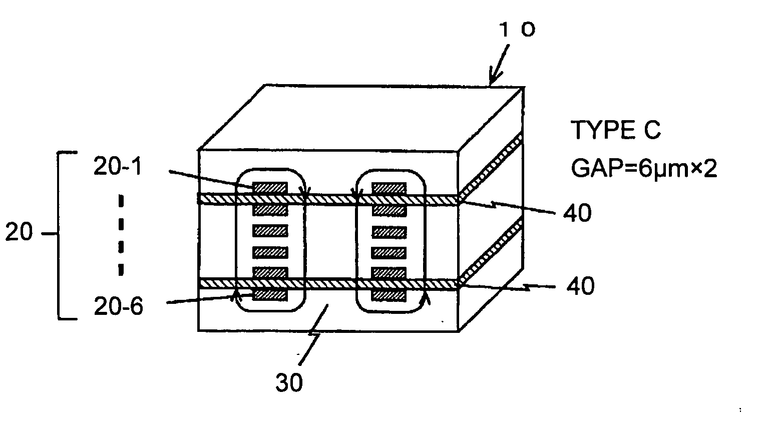
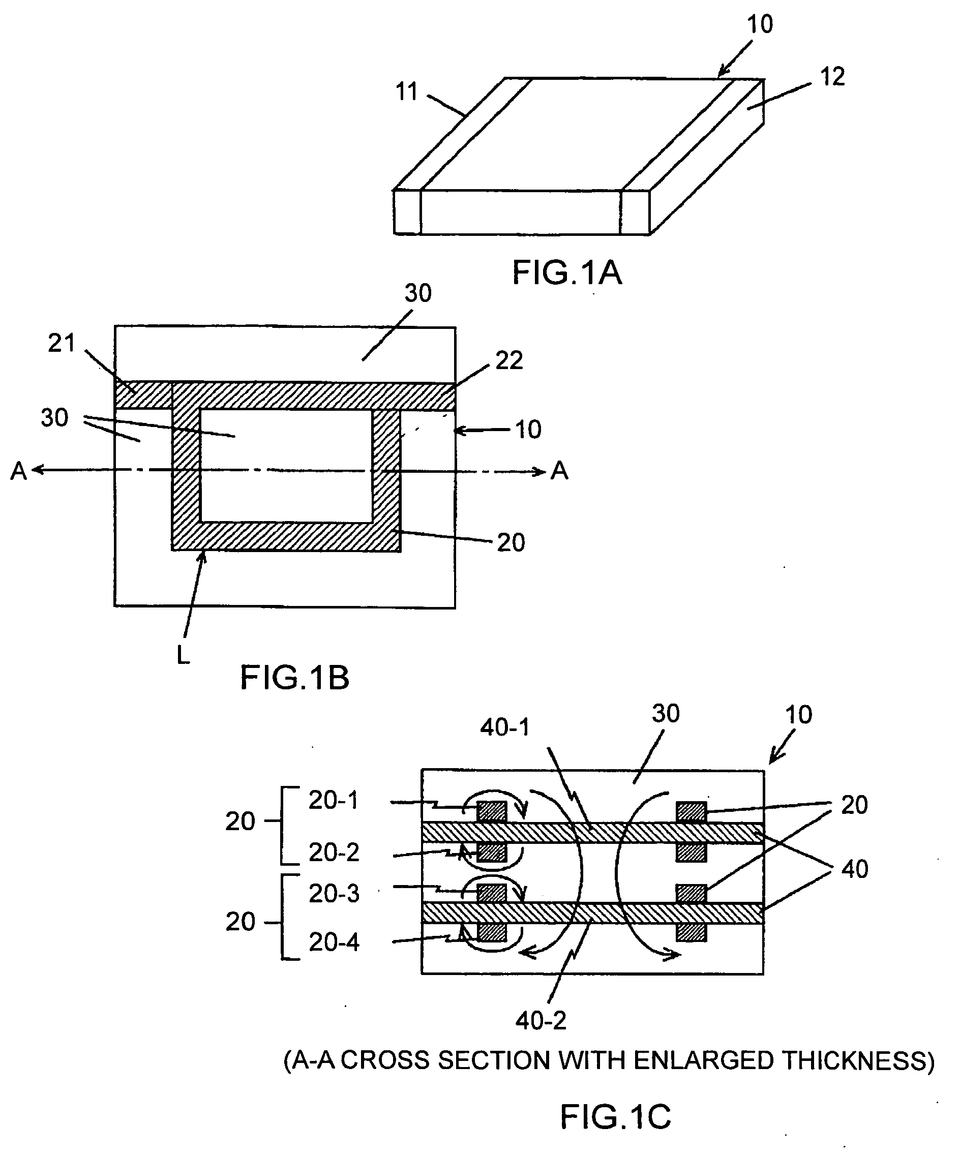
[0042]FIGS. 1A to 1C show a configuration of a magnetic core type laminated inductor of a first implementation of the present invention, in which FIG. 1A is a perspective view showing an external configuration, FIG. 1B is a top plan view showing conductive patterns, and FIG. 1C is a cross-sectional view taken along the A-A line in FIG. 1B while emphasizing and enlarging the cross section in the thickness direction.

[0043] A magnetic core type laminated inductor 10 shown in the drawings is formed as a surface mounting chip component. This magnetic core type laminated inductor 10 is formed by laminating electrical insulating magnetic bodies (soft magnetic bodies) 30 and conductive patterns 20 alternately by screen printing or the like. The conductive patterns 20 overlap in the layer direction in the electrical insulating magnetic bo...


PUM

PropertyMeasurementUnit
rated currentaaaaaaaaaa
magneticaaaaaaaaaa
magnetic fieldaaaaaaaaaa

Abstract

In a magnetic core type laminated inductor, magnetic gap layers are interposed between layers of conductive patterns, and the magnetic gap layers are formed separately on multiple layers mutually distant from each other while sandwiching a magnetic body layer. Moreover, the multiple magnetic gap layers are vertically symmetrically disposed relative to a central portion of lamination in a magnetically equivalent fashion, and the respective magnetic gap layers interpose at least two layers of the conductive patterns therebetween.

Description

CROSS-REFERENCE TO RELATED APPLICATIONS [0001] This application is a continuation of the International Application No. PCT / JP2004 / 010752 filed on Jul. 22, 2004 designating the United States of America.BACKGROUND OF THE INVENTION [0002] 1. Field of the Invention [0003] The present invention relates to a magnetic core type laminated inductor. More specifically, the present invention is effective for application to a surface mounting chip inductor used in the state of direct-current superposition, and is suitable for application to a micro DC-DC converter in a mobile information device such as a mobile telephone, which is configured to convert a power supply voltage (an electromotive force) obtained from an internal battery into a given circuit operating voltage. [0004] 2. Description of the Related Art [0005] Magnetic core type inductors such as transformers or choke coils used in power circuits including DC-DC converters and the like are formed by winding coils around magnetic cores....

Claims


Application Information

Patent Timeline
Patent Type & Authority Applications(United States)
IPC IPC(8): H01F5/00H01F27/24H01F17/00H01F27/255H01F27/28H01F37/00
CPCH01F17/0013H01F27/2804H01F1/34H01F5/003
Inventor NAKAO, FUMIAKISUZUKI, KAZUNARIKITAOKA, MIKIOMATSUBAYASHI, DAISUKESUZUKI, SHIGENORI
Owner AZ ELECTRONICS MATERIALS USA CORP
Why Eureka
Try Eureka