Method of measuring occluded features for high precision machine vision metrology

a technology of occlusion and machine vision, applied in the field of machine vision inspection systems, can solve the problems of not being able to easily programmable alternatives, occlusion problems that have not been addressed, and sometimes arise, and achieve the effect of avoiding occlusion and simple operation

Active Publication Date: 2006-02-02
MITUTOYO CORP
View PDF11 Cites 21 Cited by
  • Summary
  • Abstract
  • Description
  • Claims
  • Application Information

AI Technical Summary

Benefits of technology

[0014] It will be appreciated that the methods of the present invention provide for simple operation by a user, in that standardized types of video tools may be utilized, with few, if any, customization operations. In other words, a user is not required to utilize scripting languages for implementing customized operations to avoid occluding features. Instead, the system allows for the use of pre-programmed icons and the like that even an unskilled user is able...

Problems solved by technology

In machine vision systems, “occlusion” type problems sometimes arise, that is, situations in which a foreground object interferes with the viewing or inspection of a background object.
Occlusion problems have generally not been addressed by general purpose machine vision systems for inspection and measurement of workpieces.
Previously, there have been no readily programmable alternatives.
In such cases, when inspecting images having foreground and background features, such as edge features, in close proximity in the feature to be inspected, the slightest variation in construction between various workpieces, or lighting and shadows, will cause the carefully positioned and trained tools to fail or provide erroneous results.
However, such methods are time consuming to implement and require considerable knowledge.
Furthermore, such methods are actually creating artificial features wi...

Method used


Image

  • Method of measuring occluded features for high precision machine vision metrology
  • Method of measuring occluded features for high precision machine vision metrology
  • Method of measuring occluded features for high precision machine vision metrology

Examples


Embodiment Construction

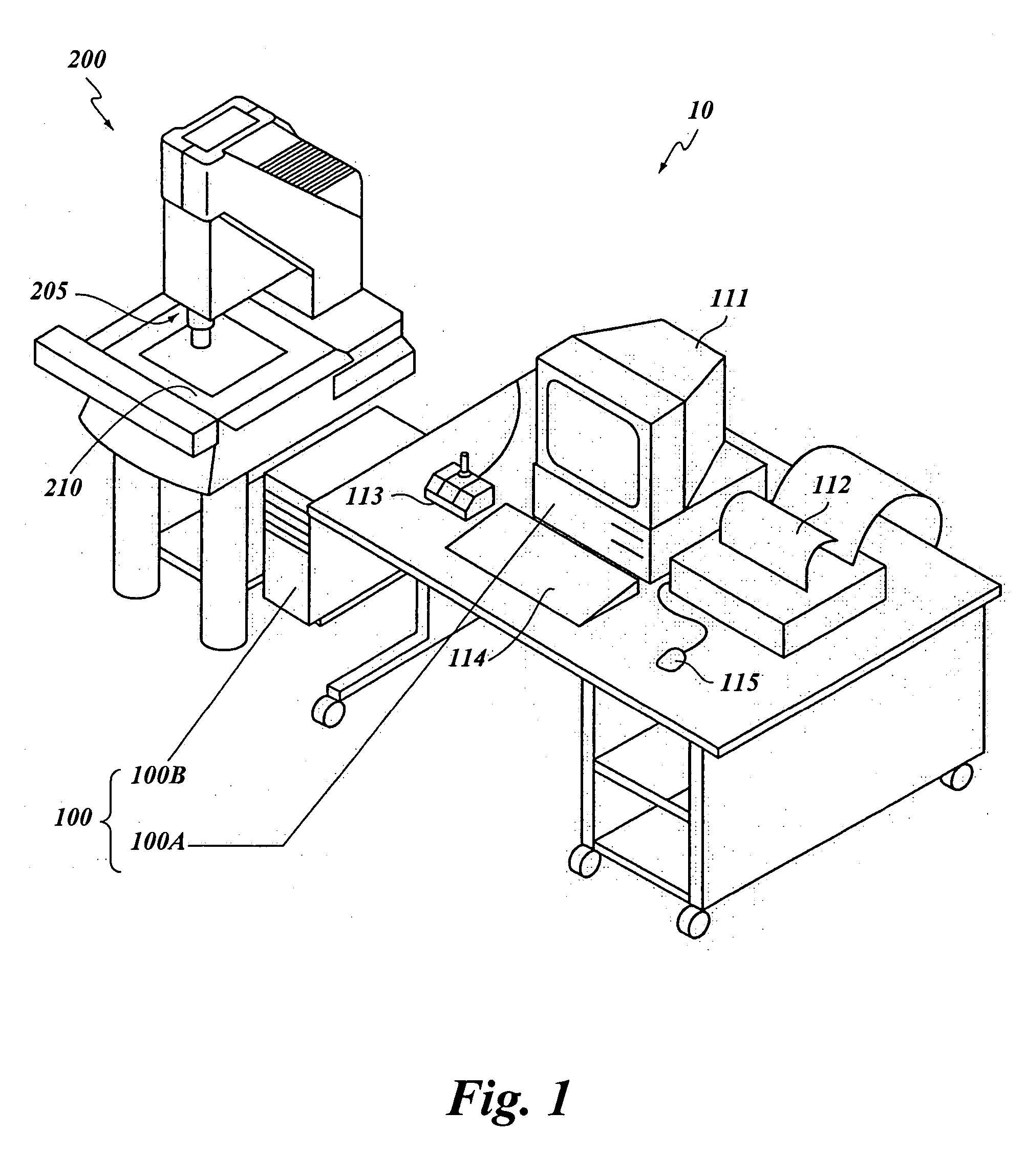
[0033]FIG. 1 is a block diagram of one exemplary embodiment of a general purpose programmable machine vision inspection system 10 in accordance with this invention. The machine vision inspection system 10 includes a vision measuring machine 200 that is operably connected to exchange data and control signals with a control system 100. The control system 100 is further operably connected to exchange data and control signals with one or more of a monitor 111, a printer 112, a joystick 113, a keyboard 114, and / or a mouse 115. The vision measuring machine 200 includes a moveable workpiece stage 210 and an optical imaging system 205 which may include a zoom lens or a number of interchangeable lenses. The zoom lens or interchangeable lenses generally provide various magnifications for the images provided by the optical imaging system 205.

[0034] The joystick 113 can typically be used to control the movement of the movable workpiece stage 210 in both the X and Y directions, which are genera...


PUM


Abstract

A method of measuring occluded features in machine vision metrology. The method allows for high precision measurement of features that are partially obscured by an extraneous object (e.g., an overlay grid of a flat panel display screen mask). The method first roughly locates the edge points of the feature to measure. In one embodiment, the rough edge location is performed by using morphology filters to delete the extraneous object (e.g., the grid) and then doing edge detection on the filtered image. Once the rough edge locations are determined, the method then returns to the original unaltered image and for each of the roughly located edge points does edge detection in a close neighborhood of the point in the original unaltered image. These refined edge points are then used to fit the feature for highly precise measurements.

Description

FIELD OF THE INVENTION [0001] The invention relates generally to machine vision inspection systems, and more particularly to a method of measuring occluded features. BACKGROUND OF THE INVENTION [0002] Precision machine vision inspection systems can be used to obtain precise dimensional measurements of inspected objects and to inspect various other object characteristics. Such systems may include a computer, a user interface, a lighting system, a camera and optical system, and a precision stage that is movable in multiple directions to allow an operator to position the camera to image various features of a workpiece. The user interface, among other things, generally includes various video tools that are positionable on an inspection image. In this way a user of the machine vision inspection system can position and operate the video tools to perform image processing operations that are useful for various control and inspection operations, while having little or no knowledge of image p...

Claims


Application Information

Patent Timeline
IPC IPC(8): G06K9/00G06K9/48G06K9/40G06V10/44
CPCG06K9/4604G06K9/50G06T7/0004G06T2207/30164G06T7/0091G06T2207/10016G06T2207/30148G06T7/0083G06T7/12G06T7/155G06V10/44G06V10/421
Inventor TESSADRO, ANA
Owner MITUTOYO CORP
Why Eureka
Try Eureka