Supercharge Your Innovation With Domain-Expert AI Agents!

Temperature control device

A temperature control device and control signal technology, which is applied to measurement devices, electrical devices, thermometers, etc., can solve the problems of low accuracy of temperature control devices, and achieve the effect of overcoming low accuracy and improving temperature control accuracy.

Inactive Publication Date: 2015-11-25
PEKING UNIV FOUNDER GRP CO LTD +1
View PDF7 Cites 0 Cited by
  • Summary
  • Abstract
  • Description
  • Claims
  • Application Information

AI Technical Summary

Benefits of technology

The technical effect that this new technology solves by sending signals with high precision instead of just one bit at once. This means more accurate temperatures can be achieved through precise timing or adjustment compared to older methods like thermostats.

Problems solved by technology

This patented technical problem addressed in this patents relates to improving the efficiency and consistency of producing different products through thermal processing (PT). Specifically, there is a strong issue that arises when trying to accurately measure the temperatures inside liquids due to factors such as poor conductivity or lack of stable power sources for electronic devices. To solve these issues, current methods involve complex circuits involving multiple components, leading to increased complexity and potential errors caused from external influences.

Method used


Image

  • Temperature control device
  • Temperature control device
  • Temperature control device

Examples


Embodiment Construction

[0019] The present invention will be described in detail below with reference to the accompanying drawings and in combination with embodiments.

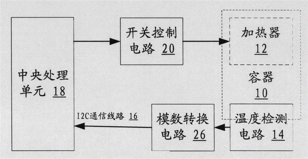
[0020] figure 1 A schematic structural diagram of a temperature control device provided in an embodiment of the present invention, including:

[0021] The temperature detection circuit 14 is arranged in the container 10 where the heater 12 is located;

[0022] The analog-to-digital conversion circuit 26 is arranged locally on the temperature detection circuit 14, and the analog signal input end of the analog-to-digital conversion circuit 26 is connected to the analog signal output end of the temperature detection circuit 14;

[0023] central processing unit 18;

[0024] The I2C communication line 16 connects the digital signal output end of the analog-to-digital conversion circuit 26 to the digital signal input end of the central processing unit 18;

[0025] The switch control circuit 20 has its control terminal connected to the c...


PUM


Abstract

The invention relates to a temperature controlling device which comprises a temperature detection circuit arranged in the container where a heater locates; an analog-to-digital conversion circuit arranged on the locality of the temperature detection circuit, the input end of an analog signal of the analog-to-digital conversion circuit is connected with the output end of the analog signal of the analog-to-digital conversion circuit; a central processing unit; an I2C (inter-integrated circuit) telecommunication line capable of connecting the output end of a digital signal of the analog-to-digital conversion circuit to the input end of the digital signal of the central processing unit; an off-on control circuit , the control terminal of the off-on control circuit is connected with the output end of a signal controlling of the central processing unit, the input end of the signal controlling of the central processing unit is connected with a power supply, and the output end is connected with the input end of the heater. The temperature controlling device improves the accuracy of the temperature controlling.

Description


Claims


Application Information

Patent Timeline
Owner PEKING UNIV FOUNDER GRP CO LTD
Features
  • R&D
  • Intellectual Property
  • Life Sciences
  • Materials
  • Tech Scout
  • Unparalleled Data Quality
  • Higher Quality Content
  • 60% Fewer Hallucinations
Learn More