Pulse width modulation (PWM) hysteresis control method based on ripple

A hysteresis control and ripple technology, applied in the field of DC switching power supply control, can solve problems such as difficult control circuit design, complex compensation circuit design and debugging, and reduced dynamic characteristics, so as to achieve good load disturbance resistance and dynamic characteristics, eliminate Phase delay problem, the effect of reducing the number of components

Inactive Publication Date: 2015-02-25
SHANGHAI UNIVERSITY OF ELECTRIC POWER
View PDF4 Cites 0 Cited by
  • Summary
  • Abstract
  • Description
  • Claims
  • Application Information

AI Technical Summary

Problems solved by technology

However, when this control method has a sudden change in the load, due to the delay lag caused by the compensation circuit of the voltage error amplifier in the control circuit, it not only causes its transient response to be slow, but also reduces its dynamic characteristics.
Moreover, the compensation circuit of the voltage error amplifier is more complicated to design and debug
These problems have brought great difficulties to the design of the control circuit.
[0003] In the traditional PWM voltage control method, the triangular carrier generation circuit, operational amplifier and corresponding compensation circuit are used, which increase the size of the conversion circuit and make it difficult to achieve miniaturization and light weight; the error characteristics of the operational amplifier seriously affect the control circuit. performance
Make the designer spend a lot of time and manpower and material resources when solving the stability problem of the operational amplifier; in the traditional PWM voltage control method, adjusting the phase compensation circuit is to improve the load variation characteristics through the gain and bandwidth of the error amplifier. These designs are relatively Complicated and not easy to do; the traditional hysteresis PWM control method does not use the idea of ​​inductor current ripple and capacitor parasitic resistance ripple voltage to lead to feedback
The performance of the DC conversion circuit cannot be optimized

Method used


Image

  • Pulse width modulation (PWM) hysteresis control method based on ripple
  • Pulse width modulation (PWM) hysteresis control method based on ripple
  • Pulse width modulation (PWM) hysteresis control method based on ripple

Examples


Embodiment Construction

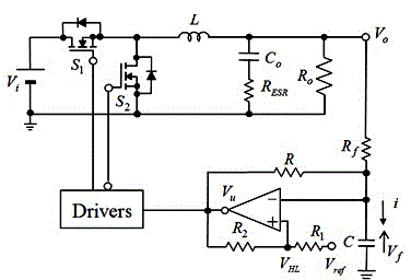
[0026] Such as figure 1 Shown is the traditional hysteresis control method diagram, V o Is the output voltage; Io is the load current; R o for the load; R f and R Adjust resistors for feedback; V i is the input voltage; S 1 , S 2 MOSFET is the switching tube; L is the filter inductance; C is the capacitance; V f for capacitance C voltage on C o is the filter capacitor; R ESR is the parasitic resistance of the filter capacitor, V ESR is the parasitic resistance of the filter capacitor R ESR on the voltage; V L and V H The hysteresis comparator threshold voltage (low level, high level) is in the figure V HL , V ref is the reference voltage;R 1 ,R 2 Adjust resistors for upper and lower thresholds. The positive and negative ends of the input DC power supply are connected in series with two MOSFET switch tubes S 1 and S 2 , the driver is connected to two MOSFET switch tubes S 1 and S 2 Control pole, the series connection point of two MOSF...


PUM


Abstract

The invention relates to a pulse width modulation (PWM) hysteresis control method based on a ripple. On the basis of traditional hysteresis control, with the help of the feedback of an introduction of the inductor ripple current and the capacity parasitic resistance ripple voltage, a transient response of the hysteresis control is greatly improved and anti-load disturbance capability and dynamic characteristics are better. According to the PWM hysteresis control method based on the ripple, due to the fact that only a hysteresis comparator and a feedback regulation resistor are needed, the number of components of a control circuit is greatly reduced, and cost and size are greatly reduced. Moreover, due to the fact that an error amplifier is not used, when phase delay caused by a compensation circuit is eliminated, the dynamic characteristics of a control circuit are also effectively improved. The PWM hysteresis control method based on the ripple has the advantages of being fast in transient response of output voltage, low in overshoot, and short in convergence time.

Description

technical field [0001] The invention relates to a DC switching power supply control method, in particular to a ripple-based PWM hysteresis control method. Background technique [0002] With the rapid development of communication technology, the volume of DC switching converters is getting smaller and smaller, the efficiency is getting higher and higher, the power density is getting higher and higher, and the requirements for dynamic load performance are becoming more and more stringent. Especially in low-voltage and high-current applications, how to design a power supply that meets the requirements is a major challenge in the field of power electronics. These challenges put forward higher requirements for the voltage regulator module (Voltage Regulator Module, VRM) of the DC switching converter: (1) fast dynamic response to the load (2) high voltage regulation accuracy (3) high power conversion efficiency. These pose new challenges to the control technology of the DC conver...

Claims


Application Information

Patent Timeline
Patent Type & Authority Patents(China)
IPC IPC(8): H02M3/155
Inventor 赵晋斌戴剑丰刘永晓
Owner SHANGHAI UNIVERSITY OF ELECTRIC POWER
Why Eureka
Try Eureka