Oil and gas suspension system and engineering vehicles

A technology of oil-pneumatic suspension and left suspension, which is applied to vehicle components, suspensions, elastic suspensions, etc. It can solve the problems that cannot fully meet the requirements of complex roads and driving conditions, and the stiffness and damping characteristics of the suspension system cannot be actively adjusted. To achieve the effect of optimizing the shock absorption effect, continuously adjusting the height of the vehicle, and reducing the degree of left and right shaking

Inactive Publication Date: 2016-01-20
SANY HEAVY IND CO LTD (CN)
View PDF6 Cites 0 Cited by
  • Summary
  • Abstract
  • Description
  • Claims
  • Application Information

AI Technical Summary

Problems solved by technology

[0003] In view of this, the present invention aims to propose an oil-pneumatic suspension system and an engineering vehicle to solve the problem that the stiffness and damping characteristics of the suspension system cannot be actively adjusted and cannot fully meet the requirements of complex roads and driving conditions

Method used


Image

  • Oil and gas suspension system and engineering vehicles
  • Oil and gas suspension system and engineering vehicles
  • Oil and gas suspension system and engineering vehicles

Examples


Embodiment 1

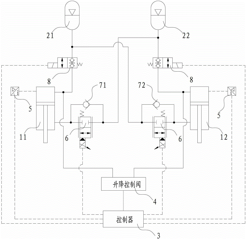
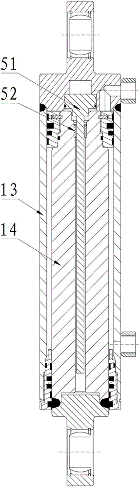
[0032] figure 1 and figure 2 That is the relevant drawings of this embodiment, as shown in the figure, the oil-pneumatic suspension system described in this embodiment includes a controller 3, a lifting control valve 4, a suspension cylinder, an accumulator, two position sensors 5, two Directional control valve 8, left damping device, right damping device, left one-way valve 71 and right one-way valve 72. Wherein, the suspension oil cylinder includes two left suspension oil cylinders 11 and 12 right suspension cylinders, and the accumulator includes two left accumulators 21 and 22 right accumulators, and the directional control valve 8 is a normally closed valve controlled by the controller 3. Two-position two-way solenoid valve. The left damping device and the right damping device are two electric proportional valves 6 controlled by the controller 3 . The lifting control valve 4 is an electromagnetic reversing valve controlled by the controller 3. The lifting control valv...

Embodiment 2

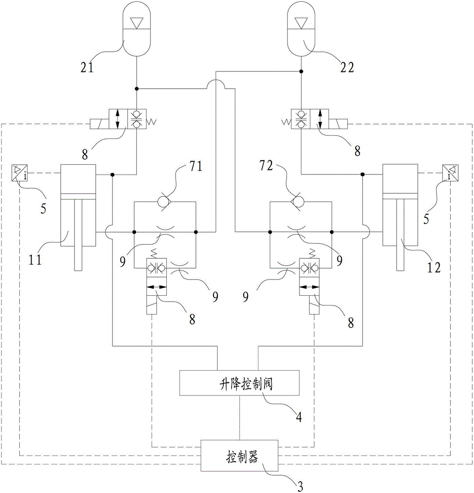
[0039] image 3 That is the relevant drawings of this embodiment, as shown in the figure, except for the damping device, the rest of the structure of this embodiment is completely consistent with that of Embodiment 1. The left damping device and the right damping device in this embodiment are both multi-stage damping switching valves, and the multi-stage damping switching valve includes two mutually parallel damping holes 9 and a directional control valve 8, and this directional control valve 8 is connected to one of them. The damping holes 9 are connected in series. The directional control valve 8 is also a two-position two-way solenoid valve controlled by the controller 3 , and the damping can be adjusted stepwise by controlling the on-off of the directional control valve 8 .

[0040] As other modified implementations of this embodiment, the damping device can be more than two damping holes 9 connected in parallel with each other, and there can also be multiple directional ...


PUM


Abstract

The invention provides an oil-pneumatic suspension system and an engineering vehicle. The oil-pneumatic suspension system includes a suspension oil cylinder and an accumulator. In communication, an adjustable damping device is provided on the oil path from the rod cavity of the suspension cylinder to the accumulator. The oil-pneumatic suspension system of the present invention is provided with an adjustable damping device, so the damping force can be adjusted in real time according to different road conditions, the shock absorption effect under different road conditions can be optimized, and the requirements of different road conditions can be better adapted.

Description

technical field [0001] The invention relates to the field of engineering machinery, in particular to an oil-air suspension system and an engineering vehicle. Background technique [0002] Oil-air suspension is a suspension device that uses oil to transmit pressure, uses inert gas (usually nitrogen) as the elastic medium, and uses throttle holes, check valves, etc. as shock absorber components. Ride comfort and vehicle driving stability have been widely used in many wheeled engineering vehicles, such as all-terrain cranes, mining dump trucks, and missile transport vehicles. At present, most of the oil-pneumatic suspensions used in engineering vehicles belong to the category of passive suspension. During the driving process of the vehicle, its stiffness and damping characteristics cannot be actively adjusted, and cannot fully meet the needs of complex roads and driving conditions (such as driving on a highway. In order to improve the stability of the car body, it is necessary...

Claims


Application Information

Patent Timeline
Patent Type & Authority Patents(China)
IPC IPC(8): B60G17/015
Inventor 邹兴龙吴永闯余明
Owner SANY HEAVY IND CO LTD (CN)
Why Eureka
Try Eureka