Pressing palm of roving frame

A roving frame and roving technology, applied in textiles and papermaking, etc., can solve the problems of reducing the risk of threading out, complex manufacturing technology, and unsatisfactory results, and achieve the effect of reliably preventing threading out

Active Publication Date: 2016-08-03
SAURER GERMANY GMBH & CO KG
View PDF8 Cites 0 Cited by
  • Summary
  • Abstract
  • Description
  • Claims
  • Application Information

AI Technical Summary

Problems solved by technology

The risk of piercing can be reduced by keeping the wings slanted, but the effect is still unsatisfactory
Moreover maintaining the precise curvature of the wings is complex in terms of manufacturing technology

Method used


Image

  • Pressing palm of roving frame
  • Pressing palm of roving frame
  • Pressing palm of roving frame

Examples


Embodiment Construction

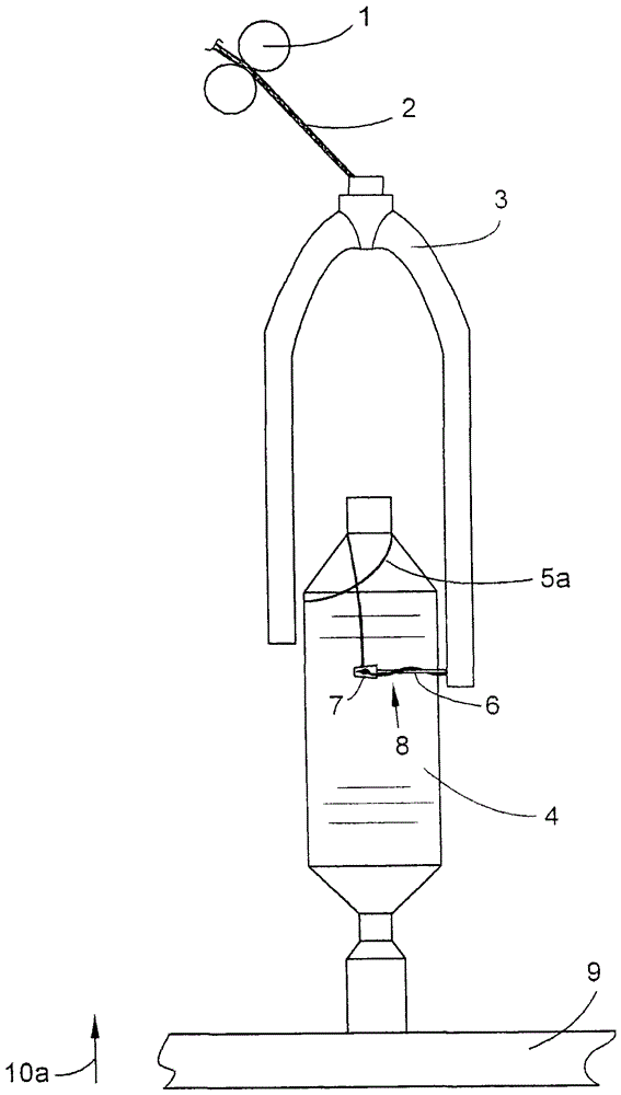
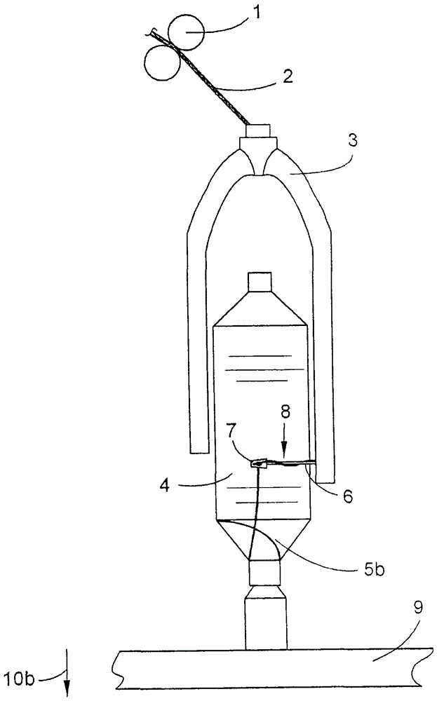
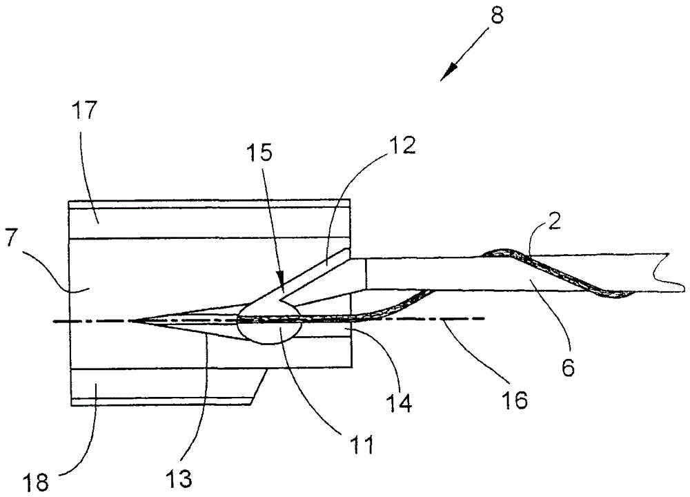
[0026] figure 1 and figure 2 Show the principle structure and working mode of the roving frame. Cooked bar is conveyed by drafting device, and wherein, only shows front roller 1 among the accompanying drawings. The drafted roving 2 is introduced into roving flyers 3, passing through one of the flyers up to its lower end. Presser palm 8 is installed on the flyer. The roving 2 is wrapped around the presser arm 6 and passed through the opening 11 in the presser leaf 7 . The roving bobbins 4 are arranged on the dragon tendons 9 . Longjin 9 can move up and down. The roving 2 obtains the required twist through the rotation of the flyer 3 and the roving bobbin 4, and is wound on the bobbin 4 under the guidance of the presser palm 8. In order to distribute the roving 2 over the axial length of the bobbin 4, the bobbin 4 is then moved up and down by means of the ribs 9.

[0027] When the bobbin 4 has reached the desired diameter, the end rovings 5a, 5b with less twist are reali...


PUM


Abstract

The pressure finger (8) has a press-finger platform (7) which is provided with openings for roving element (2). The slots are opened so as to introduce the roving elements in the opening. The slots are inclined at an angle less than 45 degree with respect to running direction of the roving elements. The longitudinal dimension of opening is greater than the transverse extensions. The distance of mouth region of slot from the end of the longitudinal extension in running direction of roving element is greater than half of the transverse dimension.

Description

technical field [0001] The invention relates to a presser finger of a roving frame comprising a presser arm and a presser leaf and for guiding the movement of roving during bobbin formation on said roving frame. The presser leaf has an opening for passing the roving, the opening having a longitudinal extension in the direction of travel of the roving through the opening and a transverse extension transverse to the direction of travel of the roving. The presser leaf also has a slot merging into the opening for introducing roving into the opening, the slot forming an angle of less than 45° with the direction of travel of the roving. Background technique [0002] Roving frames (also called flyer roving frames) process the cooked sliver into rovings which are wound onto so-called roving bobbins. The roving bobbins can be further processed into yarn on the ring spinning machine. On the roving frame, the cooked sliver first passes through the drafting unit. The roving is then d...

Claims


Application Information

Patent Timeline
Patent Type & Authority Patents(China)
IPC IPC(8): D01H7/32
CPCD01H9/046D01H7/32
Inventor F·马切尼克卡尔-海因茨·麦克
Owner SAURER GERMANY GMBH & CO KG
Why Eureka
Try Eureka