A combined structure of a lift pump room and a rear ozone contact pool

A technology for ozone contact pools and structures, applied in drainage structures, buildings, industrial buildings, etc., can solve the problems of pipelines and equipment being easily corroded by ozone, high operation and maintenance costs, and unfavorable safe operation of water plants, etc. The effect of opening times, reducing mutual interference, and facilitating production management

Active Publication Date: 2016-06-29
SHANGHAI MUNICIPAL ENG DESIGN INST GRP
View PDF4 Cites 1 Cited by
  • Summary
  • Abstract
  • Description
  • Claims
  • Application Information

AI Technical Summary

Problems solved by technology

Due to the limitation of the hydraulic elevation of the water plant, it is often necessary to increase the water level once after the water after the conventional sand filter enters the post-ozone activated carbon process. Structures such as electric rooms are set up separately. This conventional method has defects such as high investment, large land occupation, multiple equipment, and high operation and maintenance costs. The biggest defect is that the pump room needs to be equipped with a water outlet pipeline, and its water head loss accounts for about half of the pump lift. , high energy consumption, and pipelines and equipment are easily corroded by ozone
The post-ozone activated carbon process is added on the basis of the original conventional process of the waterworks. The available land in the waterworks is very tight. The lifting pump room, the post-ozone contact pool, the ozone generator room and the power distribution room are set up separately. The land utilization rate is not high. In order to arrange other structures, the design must sacrifice the storage volume of the pump room, which will bring great trouble to the operation of the water plant in the future and is not conducive to the safe operation of the water plant.
The actual operation of the current water plant using the conventional ozone activated carbon advanced treatment process has exposed these unfavorable problems

Method used


Image

  • A combined structure of a lift pump room and a rear ozone contact pool
  • A combined structure of a lift pump room and a rear ozone contact pool
  • A combined structure of a lift pump room and a rear ozone contact pool

Examples


Embodiment Construction

[0009] The present invention will be further described below in conjunction with drawings and implementation.

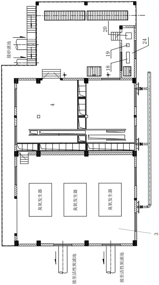
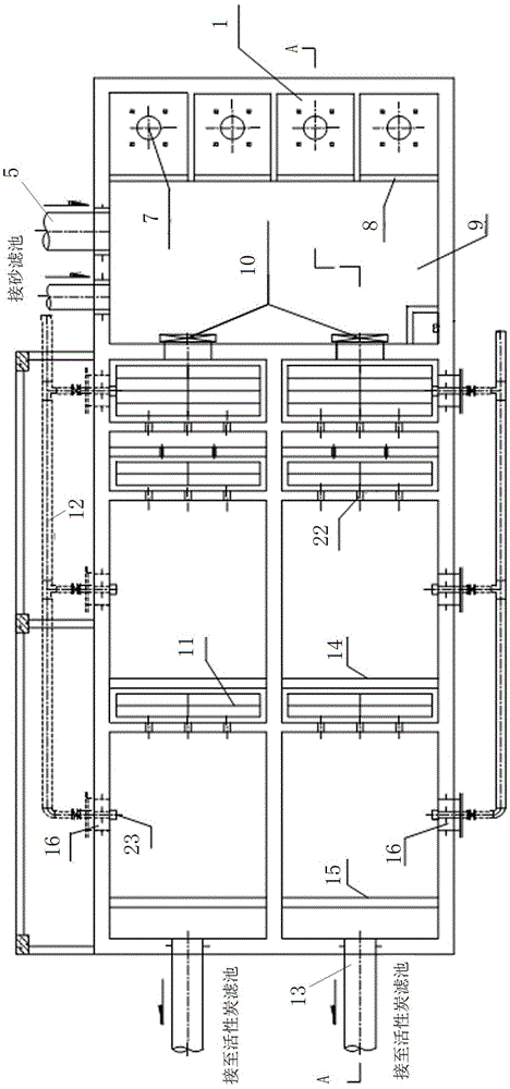
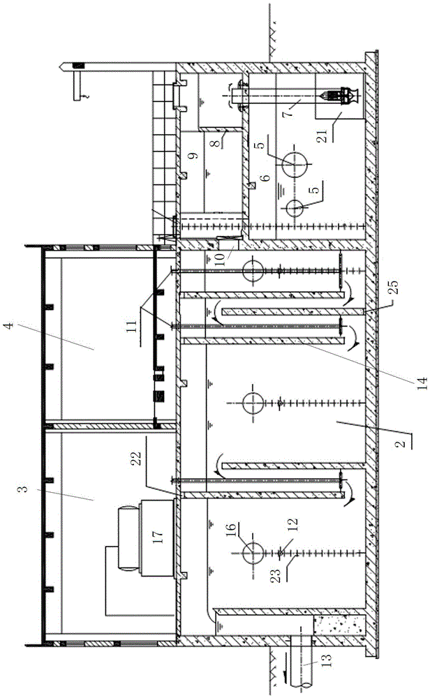
[0010] The present invention relates to a lifting pump room and a rear ozone contact pool, which mainly includes a lifting pump room 1, a rear ozone contact pool 2, and an ozone generator room 3 and a power distribution room 4 jointly built with it. The lifting pump Room 1 includes upper and lower floors, the lower layer is provided with water inlet pipe 5 and water suction well 6, the upper layer is provided with water outlet confluence channel 9, and a lifting pump and well shaft are arranged between the upper and lower layers to lift the water from the lower layer to the upper layer. In this embodiment , four lift pumps and shafts are provided, and four lift wells are set on the upper layer, overflow weirs 8 are set between each lift well and the outlet confluence channel, each lift well is provided with a lift pump 7, and the lower part of the lift pump is located...


PUM


Abstract

The invention discloses a lift pump house and post-ozone contact pool combined structure. The lift pump house and post-ozone contact pool combined structure is characterized in that a lift pump house suction well which is connected with a water inlet pipe is arranged on the lower layer of a lift pump house, a water outlet confluence channel is arranged on the upper layer of the lift pump house, a lift pump is arranged between the upper layer and the lower layer of the lift pump house, the water outlet confluence channel is communicated with a post-ozone contact pool, an ozone pool is communicated with a water outlet well, and the water outlet well is connected with a water outlet pipe. An ozone generator room is constructed on the upper portion of the post-ozone contact pool in a combined mode, an ozone generator is arranged in the ozone generator room, and the ozone generator is connected with an ozone gas distributing pipe in the contact pool. According to the lift pump house and post-ozone contact pool combined structure, a plurality of structures are compactly and reasonably combined, a water outlet pipeline system of the lift pump house is omitted, an ozone conveying system and an electric transmission line system are simplified, engineering occupied land and investment are saved, and operation fees are reduced; and simultaneously, the storage capacity of the lift pump house suction well is increased, frequent opening times of the water pump are reduced, production management is convenient, and operation safety is guaranteed.

Description

technical field [0001] The invention relates to a structure in the advanced treatment process of ozone activated carbon in a water supply plant, specifically a structure that combines the lifting pump house, the rear ozone contact pool, the ozone generator room (including an ozone tail gas destruction device) and the equipment in the advanced treatment process. The combined structure of the lifting pump room and the rear ozone contact pool combined with the electric room. Background technique [0002] At present, most of the advanced treatment processes in waterworks adopt the post-ozone biological activated carbon process, and it is most common to add ozone activated carbon after the existing conventional treatment process. Due to the limitation of the hydraulic elevation of the water plant, it is often necessary to increase the water level once after the water after the conventional sand filter enters the post-ozone activated carbon process. Structures such as electric ro...

Claims


Application Information

Patent Timeline
Patent Type & Authority Patents(China)
IPC IPC(8): E03F5/22E04H5/02
Inventor 郑志民雷挺邬亦俊袁煦许嘉炯
Owner SHANGHAI MUNICIPAL ENG DESIGN INST GRP
Why Eureka
Try Eureka