
Fireproof door with emergency illumination function

A technology of emergency lighting and fire doors, which is applied in the field of fire doors, can solve the problems of missing the best time to escape, not having emergency lighting, and not being able to see the fire doors clearly, so as to prevent the spread of smoke dance, be easy to implement, and reduce casualties Effect

Active Publication Date: 2015-04-22
SHENZHEN GUANGAN FIRE FIGHTING & DECORATION ENG
View PDF5 Cites 0 Cited by
  • Summary
  • Abstract
  • Description
  • Claims
  • Application Information

AI Technical Summary

Problems solved by technology

Existing fire doors usually only have the function of preventing the spread of fire and preventing the spread of smoke, and do not have the function of emergency lighting. As a result, people may not be able to see the fire doors clearly when there is a fire and power failure or when the normal lighting power supply fails. The specific location of the fire and the surrounding fire conditions, thus missing the best time to escape, causing irreparable damage

Method used


Image

  • Fireproof door with emergency illumination function
  • Fireproof door with emergency illumination function
  • Fireproof door with emergency illumination function

Examples


Embodiment 1

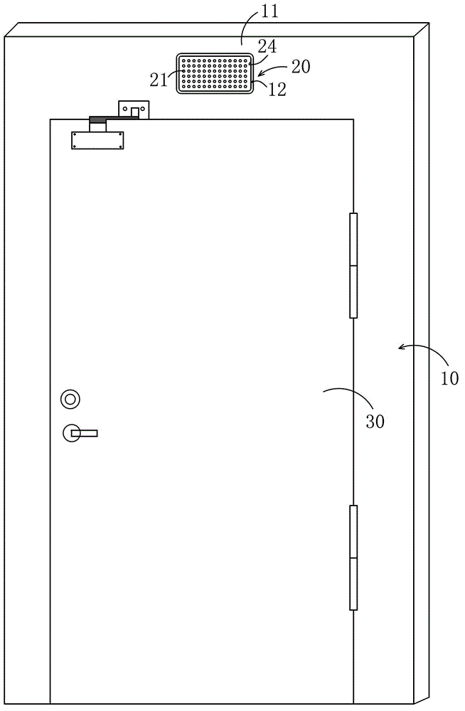
[0020] Such as Figure 5 As shown, the emergency lighting device 20 is directly connected to an external AC power source, and includes a box body, a light emitting device 21 disposed on the front side of the box body 24 , a power-off start switch 22 and a battery 23 disposed inside the box body 24 . The light emitting device 21 is a plurality of LED lamps evenly arranged on the front surface of the box body. In this embodiment, the box body 24 is a rectangular flat box body 24 made of aluminum-silicon alloy die-cast and sprayed on the surface. Such as Figure 5 As shown, the power-off start switch 22 is connected to the light-emitting device 21 and the battery 23, and is connected to the battery 23 and the light-emitting device 21 in case of emergency power-off, and the battery 23 supplies power to make the light-emitting device 21 emit light. Such as Figure 5 As shown, the power-off start switch 22 is a relay, which includes a normally open relay 221 and a normally closed...

Embodiment 2

[0023] The basic structure of the fire door with emergency lighting function is the same as that of Embodiment 1, the difference is that a concave accommodating groove 12 is provided on the rear side surface of the upper frame 11 of the door frame, and the box body 24 is fixed on the In the accommodating groove 12 , the outer surface of the box body 24 is flush with the rear surface of the door frame 10 .

Embodiment 3

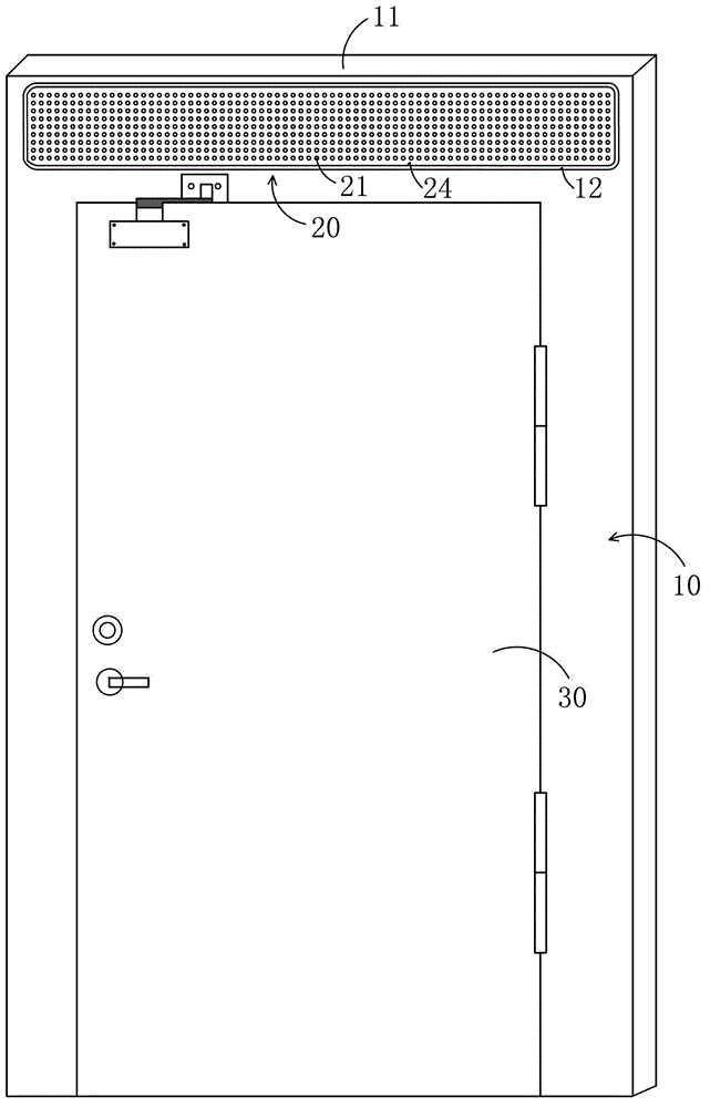
[0025] Such as image 3 , Figure 4 As shown, the basic structure of the fire door with emergency lighting function is the same as that of Embodiment 1, the difference is that the emergency lighting device 20 is mounted and fixed on the upper frame 11 of the door frame by a known wall hanging method such as screw fixing. On the front surface, it is easy to install and replace.


PUM


Abstract

The invention discloses a fireproof door with an emergency illumination function. The fireproof door comprises a door frame and a door movably connected with the door frame, and is characterized in that an emergency illuminating device which is directly connected with an external alternating-current power source is arranged on the door frame, and comprises a box, light emitting devices, a power-off starting switch and a storage battery, the light emitting devices are arranged on the front side of the box, the power-off starting switch and the storage battery are disposed inside the box, the power-off starting switch is connected with the light emitting devices and the storage battery, and the light emitting devices can be communicated with the storage battery via the power-off starting switch and are powered by the storage battery so as to emit light under an emergency power-off condition. The emergency illuminating device is arranged on the front side or the rear side of an upper border of the door frame. The fireproof door can realize the emergency illumination function under the power-off condition, and accordingly can assist personnel to orderly escape during a fire disaster. The fireproof door has the advantages of simple structure, easiness in implementation, and the like.

Description

【Technical field】 [0001] The invention relates to a fire door for building fire protection, in particular to a fire door with emergency lighting function which can provide emergency lighting to help evacuated personnel escape in an orderly manner. 【Background technique】 [0002] A fire door is a door made of fire-resistant and flame-retardant materials with high temperature resistance, airtightness and heat insulation. In the event of a fire, completely isolate the fire point from the escape route to block the spread of the fire and prevent the spread of smoke. With the increasing maturity of fire protection technology, fire doors, as a commonly used fire partition, are widely used in buildings and public places. Existing fire doors usually only have the function of preventing the spread of fire and preventing the spread of smoke, and do not have the function of emergency lighting. As a result, people may not be able to see the fire doors clearly when there is a fire and po...

Claims


Application Information

Patent Timeline
Patent Type & Authority Patents(China)
IPC IPC(8): E06B5/16F21V33/00F21V23/04F21Y101/02F21Y115/10
Inventor 李少滨叶远木
Owner SHENZHEN GUANGAN FIRE FIGHTING & DECORATION ENG
Learn More