Constant-force gate valve

A gate valve and constant force technology, which is applied in the direction of sliding valves, valve devices, engine components, etc., can solve the problems of shortening the service life of gate valves, the cone is easy to wear, and the opening size cannot be controlled, so as to prolong the service life and reduce the closing force , Open and close the effect of small force

Inactive Publication Date: 2013-04-17
SUZHOU YUDONG HVAC TECH CO LTD
View PDF6 Cites 2 Cited by
  • Summary
  • Abstract
  • Description
  • Claims
  • Application Information

AI Technical Summary

Problems solved by technology

Although such a gate valve has a simple structure and is easy to manufacture, it cannot control the opening size and can only be fully opened or fully closed, and the cone is easy to wear, which shortens the service life of the gate valve

Method used


Image

  • Constant-force gate valve
  • Constant-force gate valve
  • Constant-force gate valve

Examples


Embodiment Construction

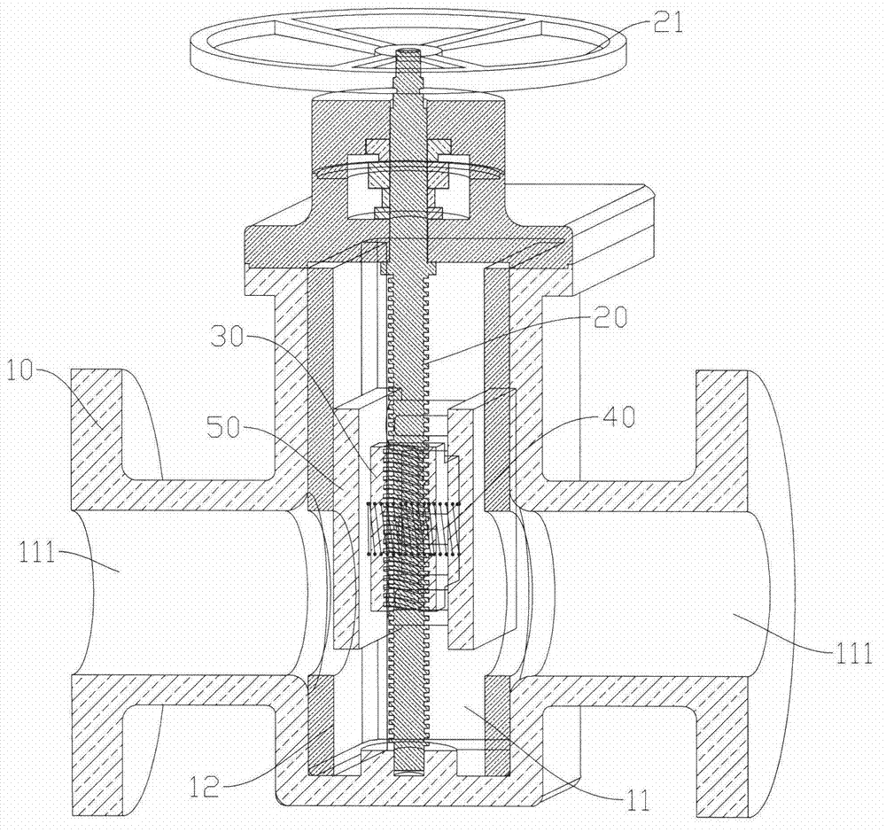
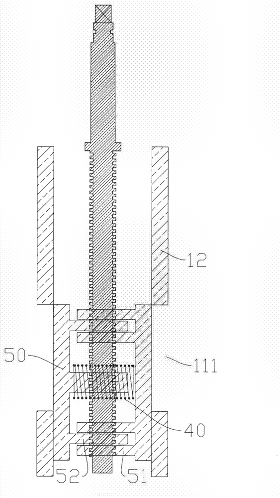
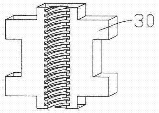
[0015] Examples, see Figure 1 to Figure 3 Shown: constant force gate valve, including valve body 10. The valve body 10 is provided with an inner chamber 11 , and the left and right ends of the inner chamber 11 are connected with water ports 111 . That is, the two water ports 111 are used to flow in and out the liquid medium. Both left and right sides of the inner cavity 11 are provided with sealing surfaces 12 . Certainly, the sealing surface 12 can be integrally formed with the valve body 10 , or can be fixed in the inner cavity 11 by means of screws or the like. The inner cavity 11 is pivotally connected with a valve stem 20, and the valve stem 20 is connected with a power device. That is, under the action of the power device, the valve stem 20 can rotate. At the same time, non-rotatable seals 50 are provided on the left and right sides of the inner cavity 11 , and the outer surfaces of the two seals 50 match the two sealing surfaces 12 respectively. The so-called matc...


PUM


Abstract

The invention discloses a constant-force gate valve comprising a valve body. The valve body is provided with an inner cavity, the left end and the right end of the inner cavity are both connected with water ports, two sealing surfaces are arranged on the left side and the right side of the inner cavity, a stem is pivoted inside the inner cavity and connected with a power device, two non-rotatable sealing elements are arranged on the left side and the right side of the inner cavity respectively, the outer side surfaces of the two sealing elements are matched with the two sealing surfaces respectively, a pressure spring is arranged between the two sealing elements, a spool is clamped between the two sealing elements in a non-rotatable manner and is in screw joint fit with the stem. The constant-force gate valve has the advantages of controllability in opening size and long service life.

Description

technical field [0001] The invention relates to the technical field of valves, in particular to a constant force gate valve. Background technique [0002] A gate valve is a valve in which the closing member (gate) moves along the vertical direction of the channel axis. Usually, the gate valve includes a valve body, the valve body is provided with an inner cavity, and both ends of the inner cavity are connected with water ports. A valve stem connected to the power device is also screwed in the inner cavity, and a cone is fixed at the lower part of the valve stem. In this way, the rotation of the valve stem drives the cone to move up and down in the inner cavity, so that the two nozzles are cut off or connected, thereby achieving the purpose of closing or opening the gate valve. Although such a gate valve has a simple structure and is easy to manufacture, it cannot control the opening size and can only be fully opened or fully closed, and the cone is easy to wear, which shor...

Claims


Application Information

Patent Timeline
Patent Type & Authority Applications(China)
IPC IPC(8): F16K3/14F16K3/314F16K3/316
Inventor 金哲龙
Owner SUZHOU YUDONG HVAC TECH CO LTD
Why Eureka
Try Eureka