Diagnosis method of low temperature plasma density parameter at atmospheric pressure
What is AI technical title?
AI technical title is built by Patsnap AI team. It summarizes the technical point description of the patent document.
A low-temperature plasma and plasma technology, applied in the field of plasma, can solve the problems of short service life, high environmental requirements, and high cost, and achieve the effects of long service life, low environmental requirements, and low cost
Inactive Publication Date: 2015-03-11
HARBIN INST OF TECH
View PDF8 Cites 0 Cited by
Summary
Abstract
Description
Claims
Application Information
AI Technical Summary
This helps you quickly interpret patents by identifying the three key elements:
Problems solved by technology
Method used
Benefits of technology
Problems solved by technology
[0004] The purpose of the present invention is to solve a series of problems such as low accuracy, poor efficiency, high environmental requirements, short service life, and relatively expensive cost in the measurement process of the existing plasma diagnostic method, and to provide a low-temperature plasma diagnostic method under normal pressure. Diagnosis Method of Plasma Density Parameters
Method used
Image
Click on the blue label to locate the original text in one second.
Reading with bidirectional positioning of images and text.
Examples
specific Embodiment approach 1
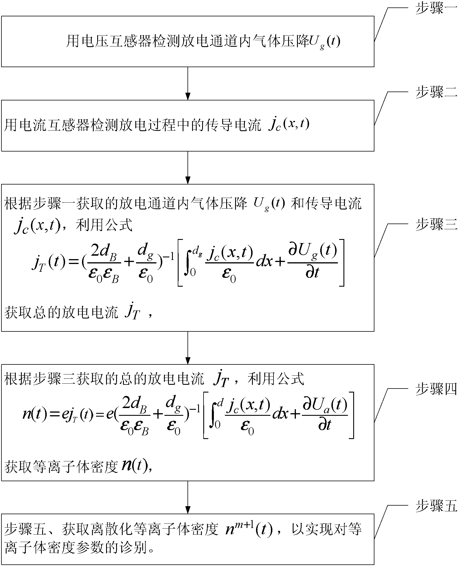
[0030] Specific implementation mode one: the following combination Figure 1 to Figure 7 Describe this embodiment, the method for diagnosing the low-temperature plasma density parameters under normal pressure described in this embodiment, the method includes the following steps:
[0031] Step 1. Use a voltage transformer to detect the gas pressure drop U in the discharge channel g (t)
[0032] Step 2: Use a current transformer to detect the conduction current j c (x, t), x=0~d g ,
[0033] In the formula: d g is the length of the discharge channel, x is the coordinate of a certain position in the discharge channel,
[0034] Step 3. According to the gas pressure drop U in the discharge channel obtained in step 1 g (t) and conduction current j c (x, t), using the formula
[0035] j T ( t ) = ( 2 ...
specific Embodiment approach 2
[0042] Specific implementation mode two: the following combination figure 2 Describe this embodiment, this embodiment will further explain Embodiment 1, and obtain the discretized plasma density n in step 5 m+1 The process of (t) is:
[0043] In the following discrete process, it is discrete into k parts, m=1, 2,...k, k is a positive integer,
[0044] Step 51, discretization of electron and ion continuity equation difference method:
[0045] n e m + 1 = n e m + j e , k + 1 / 2 m - j e , ...
PUM
Abstract
The invention relates to a diagnosis method of a low temperature plasma density parameter at an atmospheric pressure, and belongs to the field of plasma. A series of problems that the traditional diagnosis method of plasma has low precision, poor efficiency, higher environmental requirements, short service life, higher cost and the like in the measuring process are solved. The method comprises the following steps that: 1. the gas pressure drop Ug(t) in a discharge channel is detected by a voltage transformer; 2. the conduction current jc (x, t) is detected by a current transformer; 3. the total discharge current JT is obtained according to the gas pressure drop Ug (t) in the discharge channel obtained from a step 1 and the conduction current jc (x, t); 4. the plasma density n (t) is obtained according t the total discharge current jT obtained from a step 3; and 5. the discrete plasma density nm +1 (t) is obtained so as to achieve the diagnosis of the plasma density parameter.
Description
technical field [0001] The invention relates to a method for diagnosing density parameters of low-temperature plasma under normal pressure, belonging to the field of plasma. Background technique [0002] In recent years, the low-temperature plasma generated based on the principle of dielectric barrier discharge (DBD) has been widely used in many disciplines such as materials, microelectronics, chemical industry, machinery and environmental protection, and has formed a new industry - the plasma industry. For example, in materials science, technologies such as plasma physical vapor deposition (PVD), enhanced chemical vapor deposition (PECVD) and plasma source ion implantation (PSII) are usually used to prepare some luminescent, photoelectric, microelectronics, corrosion-resistant and wear-resistant materials. New multifunctional film materials such as superhard. Using plasma to modify the surface of materials to improve the wettability, water absorption, dyeability, adhesion ...
Claims
Application Information
Patent Timeline
Application Date:The date an application was filed.
Publication Date:The date a patent or application was officially published.
First Publication Date:The earliest publication date of a patent with the same application number.
Issue Date:Publication date of the patent grant document.
PCT Entry Date:The Entry date of PCT National Phase.
Estimated Expiry Date:The statutory expiry date of a patent right according to the Patent Law, and it is the longest term of protection that the patent right can achieve without the termination of the patent right due to other reasons(Term extension factor has been taken into account ).
Invalid Date:Actual expiry date is based on effective date or publication date of legal transaction data of invalid patent.


