Liquid crystal display module

A liquid crystal display module and display surface technology, which is applied in the directions of instruments, nonlinear optics, optics, etc., can solve the problems of not being able to use a large color filter glass substrate 201, not conforming to the design trend of the display's narrow frame 100, and limited size, etc. The effect of reducing the risk of surrounding light leakage and improving the display quality of the picture

Active Publication Date: 2013-04-17
BOE TECH GRP CO LTD +1
View PDF9 Cites 27 Cited by
  • Summary
  • Abstract
  • Description
  • Claims
  • Application Information

AI Technical Summary

Problems solved by technology

[0004] At present, there are two main aspects to improve the light leakage at the edge of the liquid crystal display module: on the one hand, the frame 100 is extended to the display area of ​​the liquid crystal panel as much as possible to cover the display area of ​​the liquid crystal panel, but this design does not meet the narrow frame 100 design of the current display trend; on the other hand, extend the black matrix 202 layer toward frame 100 direction, as figure 2 and image 3 shown, where figure 2 The area of ​​the black matrix 202 extends toward the frame 100, and the sealant 400 partially covers the area of ​​the black matrix 202, image 3 The area of ​​the black matrix 202 extends toward the frame 100, and the sealant 400 completely covers the area of ​​the black matrix 202, but the size of the extension of the black matrix 202 layer is limited and cannot be larger than the size of the color filter glass substrate 201, especially in the circuit terminals of the liquid crystal display module. Part (the area where the external circuit applies signals to the LCD screen), the black matrix 202 coverage area does not involve the array glass substrate 301 terminal area, and at the same time, when the sealant 400 is designed to cover part or all of the black matrix 202, it will Reduce the reliability of the entire liquid crystal display module, because the contact force between the common electrode 203 and the color filter glass substrate 201 is greater than the contact force between the black matrix 202 and the color filter glass substrate 201, when the liquid crystal module is under high temperature or under impact, it may The black matrix 202 and the common electrode 203 fall off, which may eventually lead to the separation of the glass substrate of the liquid crystal module, seriously affecting the quality of the liquid crystal module

Method used


Image

  • Liquid crystal display module
  • Liquid crystal display module
  • Liquid crystal display module

Examples


Embodiment 1

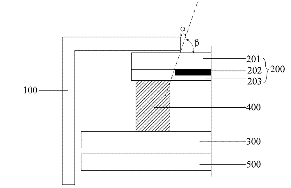
[0061] Such as Figure 5 Shown is a schematic diagram of the surrounding structure of the liquid crystal display module according to the first embodiment of the present invention, where only the array glass substrate 301 forming the array substrate 300 and the metal forming the light-shielding layer 302 are shown in the figure. signal lines, while other layers forming the array substrate 300 are not shown.

[0062] Such as Figure 5 As shown, in this embodiment, the liquid crystal display module includes a liquid crystal panel and a frame 100 arranged around the liquid crystal panel, wherein the liquid crystal panel includes a color filter substrate 200 and an array substrate 300 arranged in opposite boxes, wherein The color filter substrate 200 includes a color filter glass substrate 201, a black matrix 202 formed at a position close to the edge of the color filter glass substrate 201, and a common electrode 203 covering the black matrix 202 (for forming Other components of...

Embodiment 2

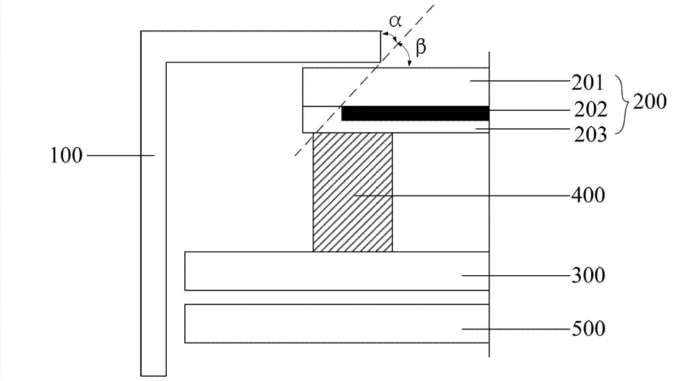
[0067] Such as Figure 6 Shown is a schematic diagram of the peripheral structure of the liquid crystal display module according to the second embodiment of the present invention, in which only the array glass substrate 301 forming the array substrate 300 and the metal signal forming the light-shielding layer are shown in the figure. lines, while other layers forming the array substrate 300 are not shown.

[0068] Such as Figure 6 As shown, in this embodiment, the liquid crystal display module includes a liquid crystal panel and a frame 100 arranged around the liquid crystal panel, wherein the liquid crystal panel includes a color filter substrate 200 and an array substrate 300 arranged in opposite boxes, wherein The color filter substrate 200 includes a color filter glass substrate 201, a black matrix 202 formed at a position close to the edge of the color filter glass substrate 201, and a common electrode 203 covering the black matrix 202 (for forming Other components of ...

Embodiment 3

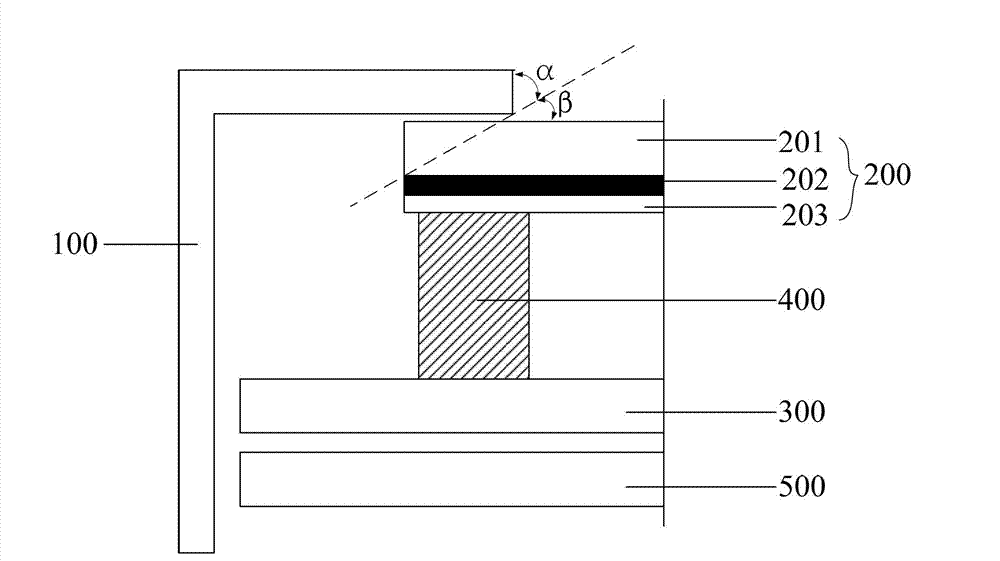
[0073] The light shielding in the liquid crystal display module in this embodiment is formed by cooperation of the second gate lines 304 and the second data lines 305 .

[0074] Such as Figure 7 Shown is a schematic diagram of the peripheral structure of the liquid crystal display module according to the second embodiment of the present invention, in which only the array glass substrate 301 forming the array substrate 300 and the metal signal forming the light-shielding layer are shown in the figure. lines, while other layers forming the array substrate 300 are not shown.

[0075] Such as Figure 7As shown, in this embodiment, the liquid crystal display module includes a liquid crystal panel and a frame 100 arranged around the liquid crystal panel, wherein the liquid crystal panel includes a color filter substrate 200 and an array substrate 300 arranged in opposite boxes, wherein The color filter substrate 200 includes a color filter glass substrate 201, a black matrix 202 ...


PUM


Abstract

The invention provides a liquid crystal display module. The liquid crystal display module comprises a liquid crystal display panel and a frame, the liquid crystal display panel comprises a color film substrate and an array substrate which are arranged in a paired box manner, a black matrix is arranged at the position of the color film substrate close to the edge, the frame is arranged on the periphery of the liquid crystal display panel, a shielding layer is arranged at the position, close to the edge, of the periphery of the array substrate, and a first included angle beta 1 formed between a connecting line from the outer edge of the shielding layer to the inner edge of the frame and a display face of the liquid crystal display panel is smaller than a second included angle beta 2 formed between a connecting line from the outer edge of the black matrix and the inner edge of the frame and the display face of the liquid crystal display panel. The liquid crystal display module shields light from a backlight source by the aid of the shielding layer arranged on the array substrate, risks of peripheral light leakage of the liquid crystal display module are reduced, and image display quality of the liquid crystal display module is improved.

Description

technical field [0001] The invention relates to the technical field of liquid crystal display, in particular to a liquid crystal display module. Background technique [0002] With the gradual popularity of Touch products and smart mobile products, the picture quality of small-sized Thin Film Transistor-Liquid Crystal Displays (TFT-LCDs) is particularly important. [0003] figure 1 Shown is a cross-sectional view of the peripheral position of a liquid crystal display module (for the sake of clarity, structures not related to this patent are not drawn), mainly including a frame 100 (Bezel), a color filter glass substrate 201 (Color Filter Glass ), the array substrate 300 (TFT), the light-shielding black matrix 202 (Black Matrix, BM) on the color filter glass substrate 201, the common electrode 203 (Indium Tin Oxides, ITO), the sealant 400 (Sealant) and the backlight 500 ( Back Light Unit, BLU). Such as figure 1 As shown, the angle α between the line connecting the outer ed...

Claims


Application Information

Patent Timeline
Patent Type & Authority Applications(China)
IPC IPC(8): G02F1/1335G02F1/1339G02F1/1362
CPCG02F1/133512G02F1/136209G02F1/13332G02F1/133388G02F1/136286G02F1/133308
Inventor 王辉叶欣秦锋
Owner BOE TECH GRP CO LTD
Why Eureka
Try Eureka