Crystal-liquid display device and pulse-wave adjusting circuit thereof

A technology for adjusting circuits and pulse waves, applied to static indicators, instruments, etc., can solve problems such as differences, affecting picture quality, and uneven brightness of sub-pixels

Active Publication Date: 2009-02-11
AU OPTRONICS CORP
View PDF7 Cites 2 Cited by
  • Summary
  • Abstract
  • Description
  • Claims
  • Application Information

AI Technical Summary

Problems solved by technology

[0011] However, this MSHD driving technique will cause the feedthrough voltages of adjacent sub-pixels to be different, resulting in a final voltage gap between odd-numbered sub-pixels and even-numbered sub-pixels, as shown in FIG. 1C
The reason is that the number of times the thin film transistors 117 of adjacent sub-pixels are turned on is different, and the thin film transistors 117 of the odd-numbered sub-pixels and the even-numbered sub-pixels are both affected by the primary feed-through voltage. Stored in the even-numbered sub-pixel liquid crystal capacitor C LC The voltage of the odd number of sub-pixel liquid crystal capacitors C LC , so that the liquid crystal capacitance C originally stored in the even numbered sub-pixels LC The voltage is reduced to half of the original, and the other half of the voltage is charged to the odd-numbered sub-pixel liquid crystal capacitor C LC , causing the final voltages of adjacent sub-pixels to be different, and the data voltage charged to each sub-pixel is different, making the brightness of each color sub-pixel uneven, which in turn affects the overall picture quality

Method used


Image

  • Crystal-liquid display device and pulse-wave adjusting circuit thereof
  • Crystal-liquid display device and pulse-wave adjusting circuit thereof
  • Crystal-liquid display device and pulse-wave adjusting circuit thereof

Examples


Embodiment Construction

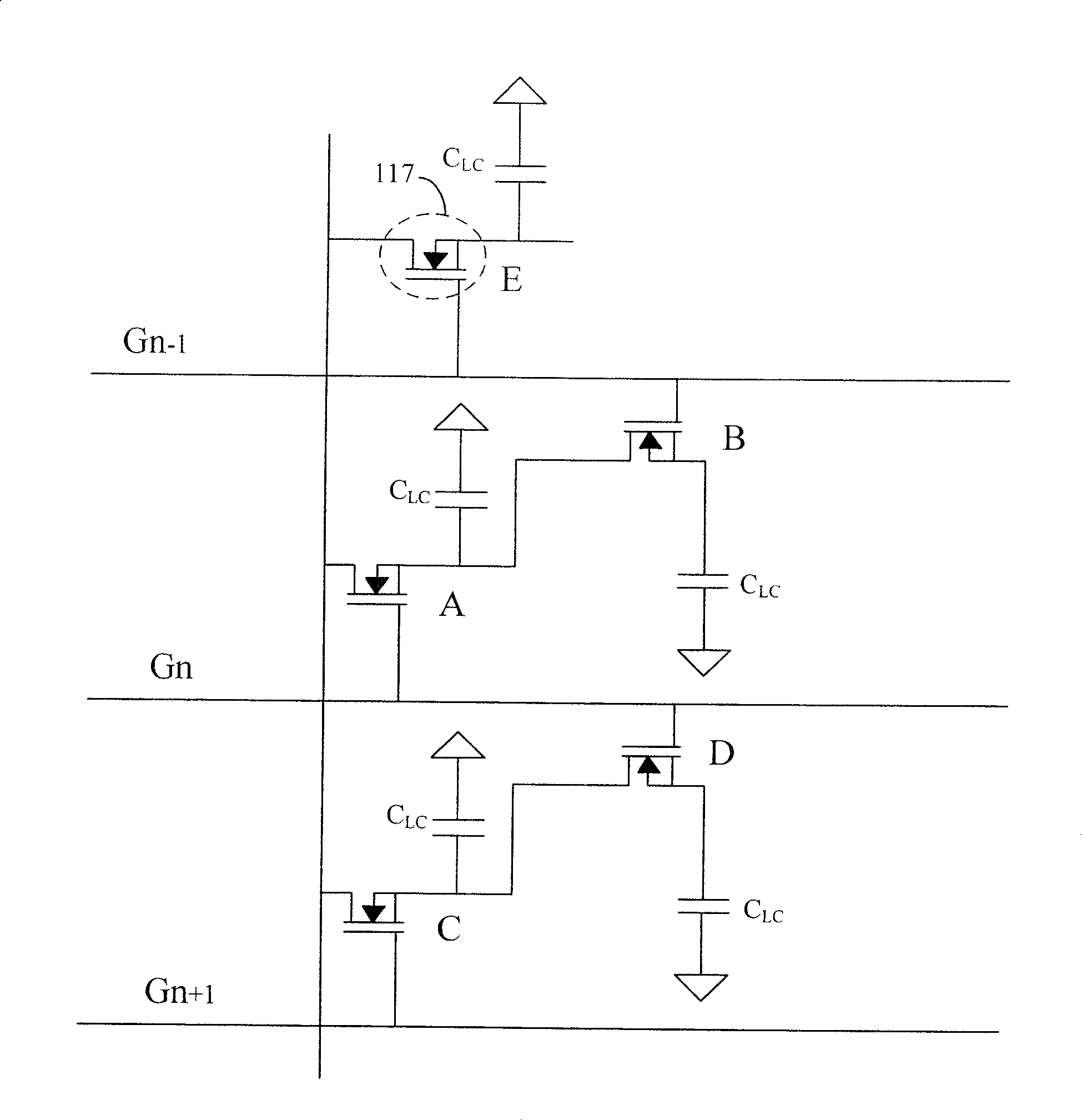
[0084] The feedthrough voltage is determined by the formula shown below:

[0085] V feedthrough = C GD C GD + C LC + C st ΔV

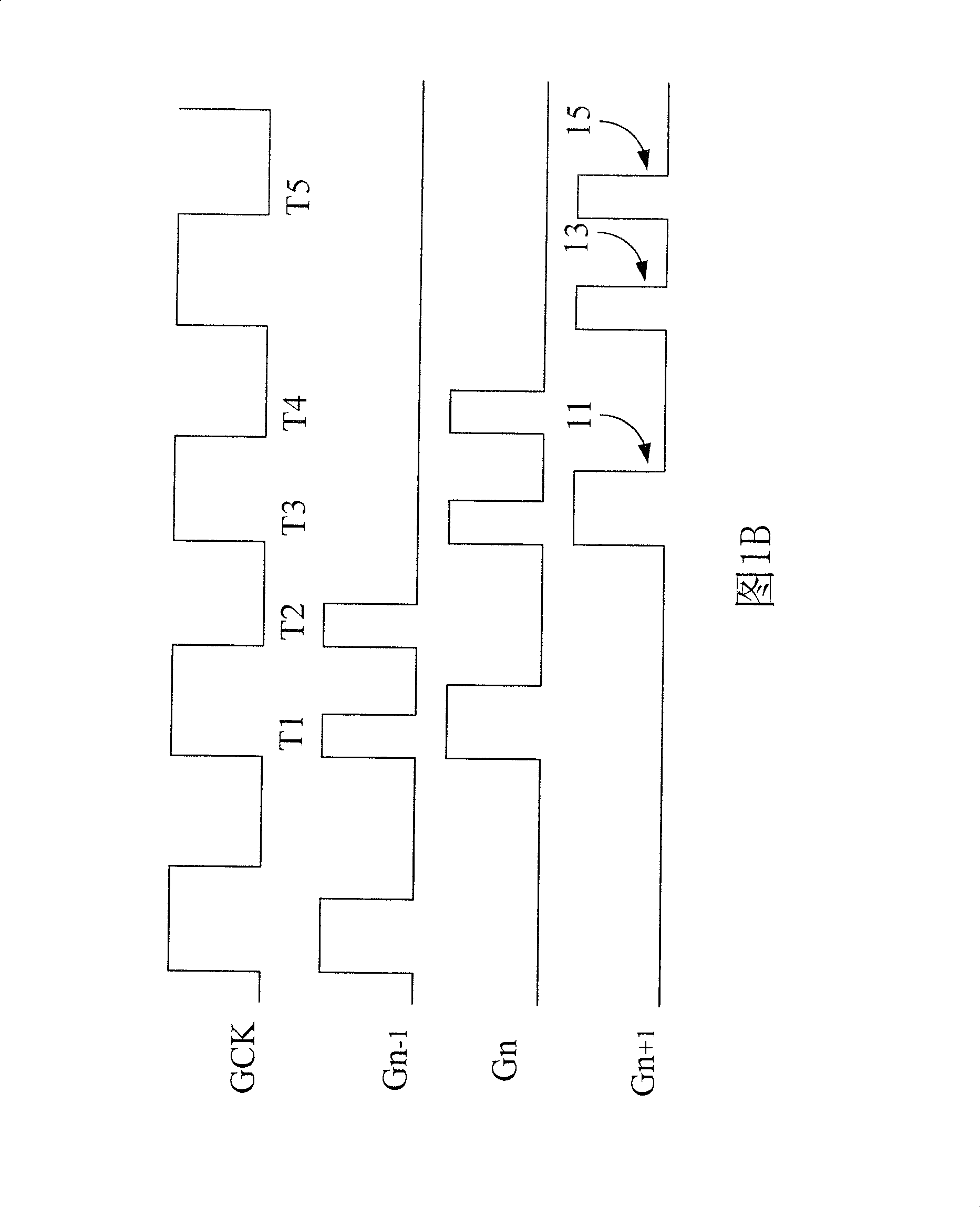
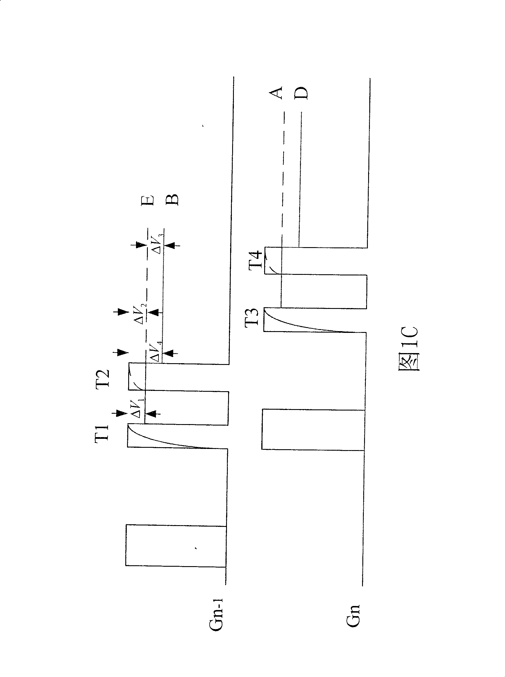
[0086] Among them, C GD is the stray capacitance between the gate and drain of the thin film transistor, C LC is the liquid crystal capacitance, C st To hold the capacitance, ΔV=(V-V GL ), V GL is the lowest level of the start signal waveform, V is the voltage at the end of the start signal waveform, and ΔV is the voltage difference at the end of the start signal waveform. When ΔV decreases, V feedthrough It will also decrease accordingly, so by reducing ΔV to reduce the feed-through voltage, the influence of the feed-through voltage on the sub-...


PUM


Abstract

A liquid crystal display is prepared as setting pulse wave regulation circuit between power supply and grid driving chip, using power supply to provide power supply signal, using pulse wave regulation circuit to regulate multiple pulse wave of power supply signal to make pulse wave have a chamfer for raising display quality of liquid crystal display face plate.

Description

technical field [0001] The present invention relates to a liquid crystal display and its pulse wave adjustment circuit. The liquid crystal display can adjust the power signal provided by the power supply to the gate drive chip in advance to reduce the feedthrough voltage difference between even sub-pixels and odd sub-pixels. Background technique [0002] With the advancement of science and technology, various electronic products have become an indispensable part of people's life. Among them, the display is an important component of multimedia electronic products. Because liquid crystal display (liquid crystal display, LCD) has the advantages of power saving, no radiation, small size, low power consumption, no space, right angle plane, high resolution, stable image quality, etc., it has gradually replaced the traditional cathode ray A tube display (cathode ray tube display, CRT display) is widely used in display panels of electronic products such as mobile phones, screens, d...

Claims


Application Information

Patent Timeline
Patent Type & Authority Patents(China)
IPC IPC(8): G02F1/133G09G3/36G09G3/20
Inventor 许文法洪集茂
Owner AU OPTRONICS CORP
Why Eureka
Try Eureka