Check patentability & draft patents in minutes with Patsnap Eureka AI!

overvoltage protection device

A technology for overvoltage protection and low-voltage equipment, which is applied in the protection of overvoltage response, emergency protection circuit device for limiting overcurrent/overvoltage, emergency protection circuit device, etc., and can solve the problem of protection level improvement

Active Publication Date: 2017-09-22
PHOENIX CONTACT GMBH & CO KG
View PDF5 Cites 0 Cited by
  • Summary
  • Abstract
  • Description
  • Claims
  • Application Information

AI Technical Summary

Problems solved by technology

In this case, due to large current changes, it is quite possible to induce a voltage in the lead of the fine protection element that is greater than the voltage limit of the idle protection element, so that the protection level increases

Method used


Image

  • overvoltage protection device
  • overvoltage protection device
  • overvoltage protection device

Examples


Embodiment Construction

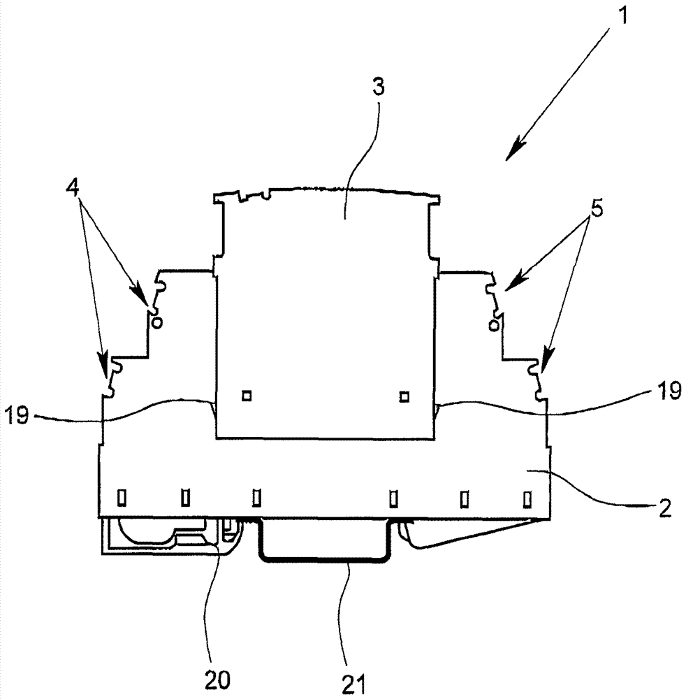
[0027] figure 1 A diagram is shown of an overvoltage protective device 1 designed as a switchgear module, which has a device base 2 and a device upper part 3 which can be plugged onto the device base 2 . The device base 2 has on its two end faces input terminals 4 and output terminals 5 which are arranged in two rows offset one above the other and are preferably designed as screw terminals or as tension spring terminals.

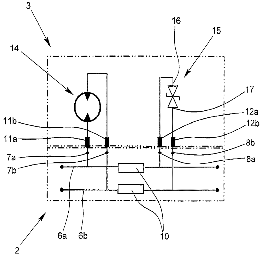
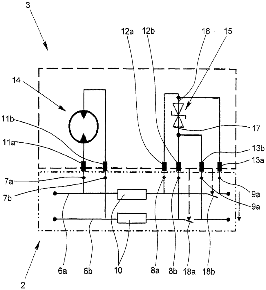
[0028] figure 2 and 3 A schematic diagram of a circuit arrangement of an overvoltage protection device 1 is shown, in which figure 2 A circuit arrangement of an overvoltage protection device 1 known from the prior art is shown in and in image 3 The circuit arrangement of the overvoltage protection device 1 according to the invention is shown in . In both figures, the two-part division between the device bottom 2 and the device top 3 is indicated by dashed lines.

[0029] from figure 2 in and from image 3 As can be seen in FIG. 2 , the input and o...


PUM


Abstract

The over-voltage protection device (1) has a fine protective element with an upper terminal with two primary counter-contact elements and lower terminal with two secondary counter-contact elements. The primary counter-contact elements comprise two contact elements in the upper line deposit, between which a primary switch is arranged. The secondary counter-contact elements comprise two contact elements in the lower line deposit, between which a secondary switch is arranged. The switches are opened when the top unit (3) is fitted on the housing base (2).

Description

technical field [0001] The invention relates to an overvoltage protection device for protecting electrical low-voltage installations, the overvoltage protection device consisting of a device base and at least one device upper part which can be plugged onto the device base, wherein the device base has an input for an electrical conductor Terminals and output terminals, at least two line paths which respectively interconnect the input terminals and output terminals assigned to each other, and contact elements connected to the input terminals and output terminals, in particular formed as sockets, wherein arranged in the line paths Longitudinal resistance, wherein the upper part of the device has opposing contact elements corresponding to the contact elements, in particular configured as pins, and at least one rough protective element connected between the two opposing contact elements, and at least one connected between two other The fine protective element between the opposing c...

Claims


Application Information

Patent Timeline
Patent Type & Authority Patents(China)
IPC IPC(8): H02H3/20
CPCH01T4/04H01T4/06H02H3/04H02H9/041H02H9/06
Inventor T.迈耶S.普费特纳
Owner PHOENIX CONTACT GMBH & CO KG
Features
  • R&D
  • Intellectual Property
  • Life Sciences
  • Materials
  • Tech Scout
  • Unparalleled Data Quality
  • Higher Quality Content
  • 60% Fewer Hallucinations
Learn More