Spring pin assembling clamp

A technology for assembling fixtures and elastic pins, which is applied to hand-held tools, manufacturing tools, workpiece clamping devices, etc., can solve the problems of time-consuming, easily lost parts, etc., and achieve the effects of simple operation, safe assembly, and simple assembly process

Inactive Publication Date: 2015-05-20
安徽鑫龙低压电器有限公司
View PDF5 Cites 2 Cited by
  • Summary
  • Abstract
  • Description
  • Claims
  • Application Information

AI Technical Summary

Problems solved by technology

[0003] In view of the defects that the traditional elastic pin assembly process takes a long time and is easy to lose parts, the technical problem to be solved by the present invention is to provide an elastic pin assembly jig that is easy to operate, high in efficiency, and will not damage parts

Method used


Image

  • Spring pin assembling clamp
  • Spring pin assembling clamp
  • Spring pin assembling clamp

Examples


Embodiment Construction

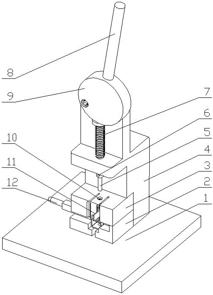
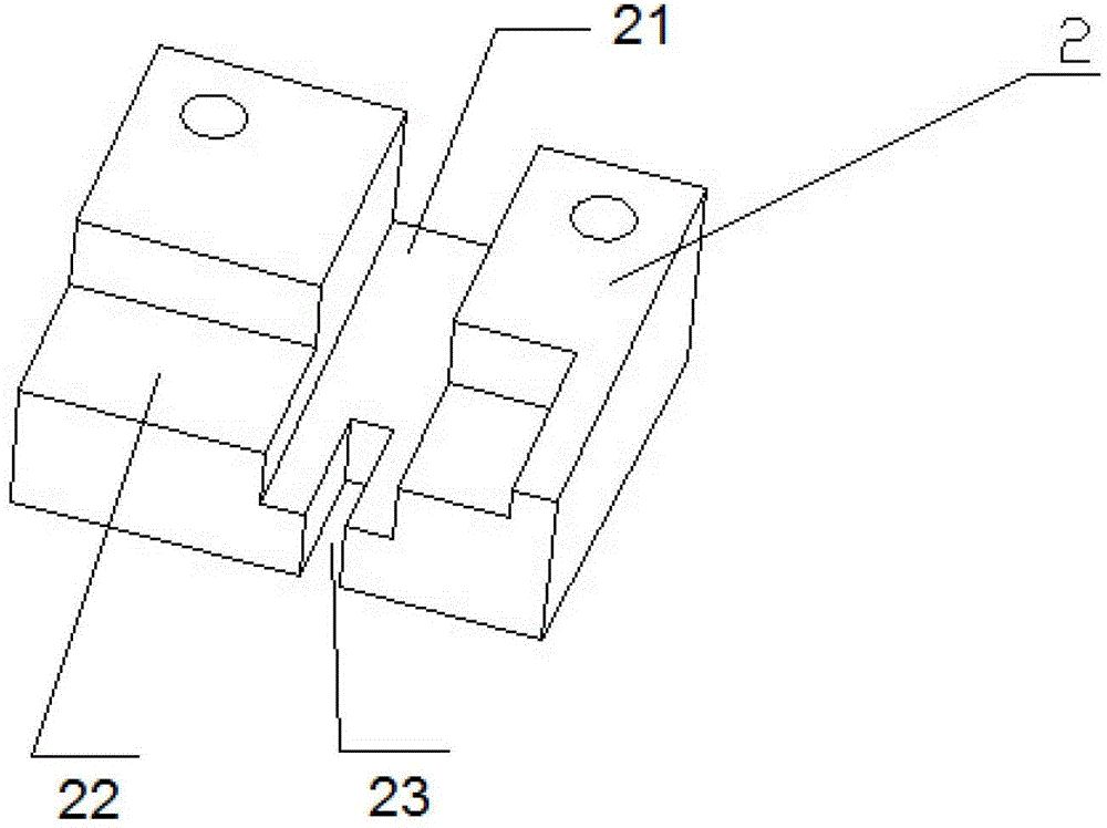
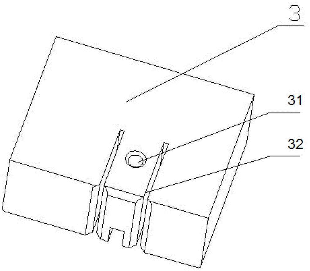
[0017] figure 1 and Figure 4 It is a structural diagram of an elastic pin assembly fixture of the present invention, including a base 1, and a backing plate 2 and a pressure plate 3 for positioning the guide plate 11 and the square shaft 12, the guide plate 11 and the square shaft 12 are located between the backing plate 2 and the Between the pressure plates 3, the backing plate 2 is fixedly connected with the base 1; the base 1 is provided with a support 4, and the support 4 is provided with a push rod 5, and the push rod 5 can slide on the support 4; The through hole 31 of the elastic pin 10, the through hole 31 and the hole on the square shaft 12 and the hole on the guide plate 11 are on the same axis;

[0018] The operating mechanism includes an eccentric wheel 9, which is located on the support 4 and can rotate on the support 4. The eccentric wheel 9 is in contact with one end of the push rod 5, and the eccentric wheel 9 is provided with a handle 8. The operating mecha...


PUM


Abstract

The invention discloses a spring pin assembling clamp. The spring pin assembling clamp comprises a base (1), a support (4), a base plate (2), a press plate (3), an ejecting rod (5), a compression spring (7), a limiting pin (6), an eccentric wheel (9) and a handle (8). A spring pin (10) is pressed into a guide plate (11) and a square shaft (12) by operating the ejecting rod (5). An assembling process and the assembling efficiency are high, the spring pin assembling clamp is safe in assembly, and assembling parts are not easily damaged.

Description

technical field [0001] The invention relates to the technical field of low-voltage electrical equipment in a power system, in particular to an elastic pin assembly fixture. Background technique [0002] The assembly process of the existing dual power supply guide parts is mainly to first pass the guide plate on the square shaft, clamp it on the bench vise, then place one end of the elastic pin in the positioning hole of the square shaft, and hit the other end of the elastic pin with a hammer , so that it is pressed into the hole of the square shaft and the hole of the guide plate, so that the guide plate and the square shaft are fixedly connected to form a guide component. Using the above method for assembly, it takes a long time to load and unload the parts, and the guide parts are complicated and easy to hurt hands, and the safety of assembly is not guaranteed; in addition, because the guide part has deep recesses, it is easy to hammer the guide parts. The above shows tha...

Claims


Application Information

Patent Timeline
Patent Type & Authority Patents(China)
IPC IPC(8): B25B27/02B25B11/02
Inventor 束龙胜叶斌闫涛胡雪松吴烟刚
Owner 安徽鑫龙低压电器有限公司
Why Eureka
Try Eureka