Damping-clearance mechanical adjustable double-coil magnetorheological valve

A magneto-rheological valve, adjustable technology, applied in the direction of mechanical equipment, fluid pressure actuators, servo motor components, etc., can solve the problems of narrow pressure adjustment range, large shape and size, pressure difference between the inlet and outlet of the valve, etc., to achieve The effect of flexible control of magnetic field strength, good control performance and wide pressure adjustment range

Inactive Publication Date: 2015-04-22
EAST CHINA JIAOTONG UNIVERSITY
View PDF7 Cites 2 Cited by
  • Summary
  • Abstract
  • Description
  • Claims
  • Application Information

AI Technical Summary

Problems solved by technology

However, the thickness of the damping gap of these three types of magnetorheological valves is fixed and cannot be adjusted, so the pressure difference between the inlet and outlet of the valve is small, the pressure adjustment range is narrow, and the adjustment method is single, which can only be used in low-pressure systems, thus hindering the magnetic flow Industrial application development of variable valve
In addition, in the structural design of some magneto-rheological valves, in order to achieve the largest possible control effect of the pressure difference between the inlet and outlet of the valve, the thickness of the damping gap is artificially designed too small or the effective damping length is increased. Small blockage, or the external structure of the valve is too large

Method used


Image

  • Damping-clearance mechanical adjustable double-coil magnetorheological valve
  • Damping-clearance mechanical adjustable double-coil magnetorheological valve
  • Damping-clearance mechanical adjustable double-coil magnetorheological valve

Examples


Embodiment Construction

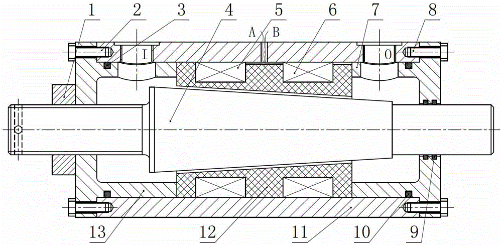
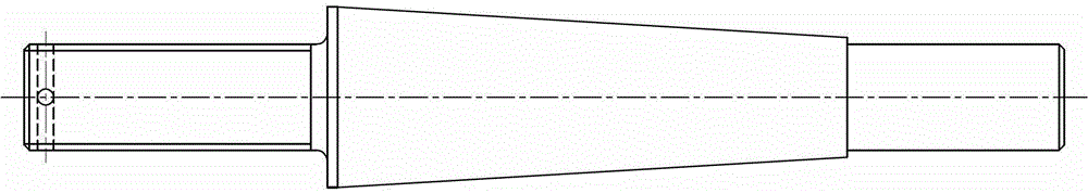
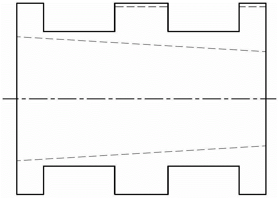
[0016] Below in conjunction with accompanying drawing and embodiment the present invention will be further described:

[0017] Such as figure 1 , figure 2 and image 3 As shown, the present invention includes: self-locking nut 1, screw I2, sealing ring I3, valve core 4, coil I5, coil II6, right end cover 7, screw II8, combined sealing ring 9, sealing ring II10, valve body 11, winding Wire frame 12, left end cover 13; left end cover 13 and valve body 11 are fixedly connected by screw I2, and sealing ring I3 is used between left end cover 13 and valve body 11; The left end surface of frame 12 is close to left end cover 13, and the right end surface of winding frame 12 is close to right end cover 7; right end cover 7 and valve body 11 are fixedly connected by screw II8, and the right end cover 7 and valve body 11 are sealed by sealing ring II10 Coil I5 is wound in the left slot of winding frame 12, lead wire A is drawn out through the lead wire slot of winding frame 12 and th...


PUM


Abstract

The invention discloses a damping-clearance mechanical adjustable double-coil magnetorheological valve which comprises an end cover, a spool, a valve block, a reel, a self-locking nut, a coil I, a coil II, a seal ring, a screw and the like. When the spool rotates to a proper position and inputs current of certain direction and certain magnitude to the coil I and the coil II, magnetic field generates in three conical damping clearances formed by the spool and the reel, and the direction of the magnetic field is substantially perpendicular to the flow direction of magnetorheological fluid. When flowing into the conical damping clearances, the magnetorheological fluid is semi-solidified fast under the action of the magnetic field, the viscosity increases fast and increases with increase of magnetic induction intensity, pressure difference between two ends of the damping clearances is caused to increase and accordingly flowing of the magnetorheological fluid can be slowed down or prevented. High pressure difference between an inlet and an outlet of the magnetorheological valve can be obtained by controlling the operating position of the spool and the magnitude and direction of the current input to the two coils. The damping-clearance mechanical adjustable double-coil magnetorheological valve is applicable to hydraulic servo control systems with wide pressure adjustment range.

Description

technical field [0001] The invention relates to a magnetorheological valve, in particular to a mechanically adjustable damping gap double-coil magnetorheological valve. Background technique [0002] In the hydraulic control system, the hydraulic control valve is mainly used to control the pressure, flow and flow direction of the liquid flow in the hydraulic actuator, so as to control the start and stop of the hydraulic actuator, change the speed, direction, force and action sequence of the movement, etc., to meet Requirements of various hydraulic equipment for load conditions such as motion, speed, force and torque. Therefore, the performance of the hydraulic control valve directly affects the static characteristics, dynamic characteristics and working reliability of the hydraulic system, and is one of the core control units in the hydraulic control system. [0003] Traditional hydraulic control valves include directional control valves, flow control valves and pressure con...

Claims


Application Information

Patent Timeline
Patent Type & Authority Patents(China)
IPC IPC(8): F15B13/02
Inventor 胡国良龙铭喻理梵李海燕黄敏
Owner EAST CHINA JIAOTONG UNIVERSITY
Why Eureka
Try Eureka