Buffering support structure

A technology of supporting structure and cover plate, applied in the field of buffer structure, can solve the problems of reduced spring life, failure of buffer structure, etc., and achieve the effects of improving lubrication, slowing down falling speed and simple structure

Inactive Publication Date: 2013-04-24
NANJING UNIV OF AERONAUTICS & ASTRONAUTICS
View PDF4 Cites 6 Cited by
  • Summary
  • Abstract
  • Description
  • Claims
  • Application Information

AI Technical Summary

Problems solved by technology

[0003] The spring support method is due to the limited working limit stress of the spring and the decreas

Method used


Image

  • Buffering support structure
  • Buffering support structure
  • Buffering support structure

Examples


Example Embodiment

[0012] Specific implementation method

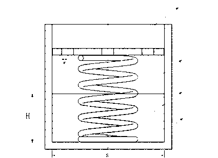
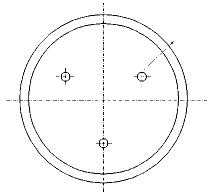
[0013] figure 1 , figure 2 The functions of each component in the are as follows:

[0014] Cover plate 1: Plays a supporting role under the action of spring 2; when spring 2 fails, it supports the transported vehicle under the action of lubricating oil 3. Spring 2: Play a buffer support role; Lubricant 3: Lubricate the cover plate 1 and cylinder 4 to prolong the service life; When the spring 2 fails, slow down the falling speed of the cover plate; Cylinder 4: Load lubricant and spring.

[0015] The following combination figure 1 , figure 2 Explain the working method of the buffer support structure of the present invention:

[0016] The cover 1 is circular, with 3 overflow holes, symmetrical along the center of the circle. Take an aero engine transport vehicle with strict requirements on the buffer support structure as an example. The buffer support structure is loaded on a transport vehicle. As the transport vehicle moves, the expansion and ...


PUM


Abstract

A buffering support structure belongs to the technical field of buffering structures. The buffering support structure is composed of a cylinder body (4), a cover plate (1) located in the cylinder body (4) to vertically slide along an inner wall of the cylinder body and a spring (2) between the cover plate and the bottom of the cylinder body. Overflow holes are evenly distributed on the cover plate (1). Lubricating oil is filled in the cylinder body, and the height of the lubricating oil is lower than the lowest position of movement of the spring. The buffering support structure can avoid damaging and failing of the spring.

Description

technical field [0001] The invention relates to a buffer support structure, which belongs to the technical field of buffer structures. Background technique [0002] In order to make the supporting structure have a buffering function, it is generally more effective to adopt spring support. The spring support is to install a spring in the support structure to form a buffer support structure. [0003] The method of adopting the spring support is due to the limited working limit stress of the spring and the decrease of the spring life due to fatigue. Once the spring is damaged, the buffer structure will fail. Contents of the invention [0004] The invention aims at the deficiencies of the prior art, and proposes a buffer support structure that avoids spring damage and failure. [0005] A buffer support structure, characterized in that: a cylinder body, a cover plate located in the cylinder body that can slide up and down along the inner wall of the cylinder body, and a sprin...

Claims


Application Information

Patent Timeline
IPC IPC(8): F16M11/00F16F15/023F16F15/04
Inventor 周正贵张金环
Owner NANJING UNIV OF AERONAUTICS & ASTRONAUTICS
Why Eureka
Try Eureka