
Clamping-sealing structure and adjustment method of transmission-type receiving probe

A technology of receiving probes, clamping and sealing, applied in the direction of the casing of the measuring device, etc., can solve the problems of alignment adjustment, anti-corrosion, poor anti-rust performance, affecting the test effect, etc., to achieve precise angle alignment adjustment, convenient and flexible replacement, structure simple effect

Inactive Publication Date: 2013-04-24
THE 45TH RES INST OF CETC
View PDF5 Cites 11 Cited by
  • Summary
  • Abstract
  • Description
  • Claims
  • Application Information

AI Technical Summary

Problems solved by technology

[0002] The work of the transmission receiving probe is in the pure water medium. The simple clamping device of the common transmission receiving probe has poor anti-corrosion and anti-rust performance, especially the adjustment work of the transmission receiving probe is also carried out in the water medium. , the airtightness of the transmissive receiving probe working in the water medium is difficult to be guaranteed during adjustment, and leakage will occur, resulting in failure, so it is impossible to adjust the alignment of the precise angle, which directly affects the test effect
In addition, the signal transmission wire connected to the receiving probe is rigidly connected, which makes it inconvenient to replace the receiving probe.

Method used


Image

  • Clamping-sealing structure and adjustment method of transmission-type receiving probe
  • Clamping-sealing structure and adjustment method of transmission-type receiving probe
  • Clamping-sealing structure and adjustment method of transmission-type receiving probe

Examples


Embodiment Construction

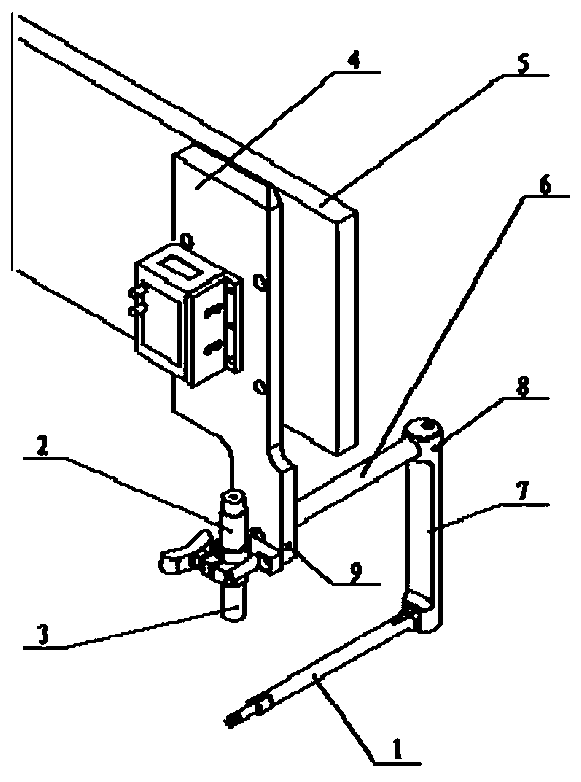
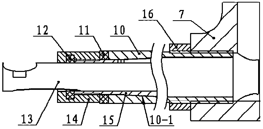
[0023] like figure 1 As shown, the clamping and sealing structure of the transmission-type receiving probe of the present invention includes a substrate 4 connected with a transmission-type transmitting probe device 2 and a structure main body 5 that fixes the substrate 4 . The bottom of the base plate 4 is provided with a shaft hole with a stop surface, and the stop shaft 6-2 with a stop surface on the left end of the upper flat rod 6 is plugged into the shaft hole with a stop surface, and the upper flat rod The stop shaft 6-2 of 6 is fixed in the shaft hole with the stop surface of the base plate 4 by a fastening screw 9. The right end head of last flat bar 6 is provided with vertical two wires up and down through notch 6-3 and a horizontal sliding notch 6-1. The right end of upper flat bar 6 is inserted in the horizontal axis hole of vertical shaft 7 upper end and is connected with vertical shaft 7 by fastening adjustment screw 8. The vertical shaft 7 is threadedly connec...


PUM


Abstract

A clamping-sealing structure and an adjustment method of a transmission-type receiving probe comprises a base plate and a structural main body, wherein the base plate is connected with a transmission-type receiving probe device and the structural main body is used for fixing the base plate. An upper flat rod fixed through a screw is inserted and connected in a shaft hole on the bottom of the base plate, inserted into a horizontal shaft hole at the upper end of a stand shaft and is connected with the stand shaft through a fastening screw. The stand shaft is in threaded connection with the transmission-type receiving probe device through a threaded hole in the lower portion of the stand shaft. The stand shaft drives the transmission-type receiving probe device to slide on the upper flat rod to adjust the distance between the receiving probe and the center of a transmitting probe emitter zone. The receiving probe device slightly rotates on the stand shaft to adjust the deviation of the receiving probe and the center of the emitter zone. According to the clamping-sealing structure and the adjustment method of the transmission-type receiving probe, the transmission-type receiving probe can be flexibly and conveniently replaced in real time or accurate angle alignment adjustment can be carried out. A water seepage phenomenon of the transmission-type receiving probe placed in the water cannot happen. The clamping-sealing structure and the adjustment method of the transmission-type receiving probe are especially suitable for nondestructive testing job requirements of transmission-type high-speed scanning.

Description

technical field [0001] The invention relates to an ultrasonic scanning detection device, in particular to a clamping and sealing structure and an adjustment method of a transmission receiving probe. Background technique [0002] The work of the transmission receiving probe is in the pure water medium. The simple clamping device of the common transmission receiving probe has poor anti-corrosion and anti-rust performance, especially the adjustment work of the transmission receiving probe is also carried out in the water medium. , It is difficult to guarantee the tightness of the transmissive receiving probe working in the water medium during adjustment, and leakage will occur, resulting in failure. Therefore, it is impossible to adjust the alignment of the precise angle, which directly affects the test effect. In addition, the signal transmission wire connected to the receiving probe is rigidly connected, which makes it inconvenient to replace the receiving probe. Contents o...

Claims


Application Information

Patent Timeline
Patent Type & Authority Applications(China)
IPC IPC(8): G01D11/26
Inventor 陶利权黄晓鹏吕荣华
Owner THE 45TH RES INST OF CETC
Learn More