Compound spring type floating socket

A composite spring and socket technology, which is applied in the direction of coupling device, base/housing, electrical components, etc., can solve the problems of poor working reliability, no sealing protection, easy dust accumulation in pores, etc., and achieve high working reliability, high reliable connection, Good anti-seismic effect

Active Publication Date: 2015-01-28
ZHEJIANG ZHONGHANG ELECTRONICS
View PDF5 Cites 0 Cited by
  • Summary
  • Abstract
  • Description
  • Claims
  • Application Information

AI Technical Summary

Problems solved by technology

[0003] The purpose of the present invention is to solve the problem that the swimming connector in the prior art can only swim on the horizontal plane of the connector and has poor anti-vibration effect, and provide a three-dimensional swimming connector with good anti-vibration effect. Composite spring type swimming socket
[0004] Another object of the present invention is to solve the problems of poor contact and poor working reliability caused by deflection and insertion in the prior art of the floating connector, and to provide a method that can eliminate the problem of poor contact caused by deflection and insertion, and has high working reliability. High composite spring type swimming socket
[0005] The third purpose of the present invention is to solve the problem that the floating connectors in the prior art have no sealing protection function, and the pores are easy to accumulate dust, which will cause blockage between the floating plate and the fixed seat and affect the flexibility of the floating plate. To solve the problem, provide a composite spring-type swimming socket that can prevent dust from entering, has a good sealing and protection effect, and ensures the flexibility of the swimming plate

Method used


Image

  • Compound spring type floating socket
  • Compound spring type floating socket
  • Compound spring type floating socket

Examples


Embodiment 1

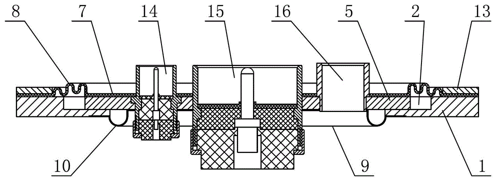
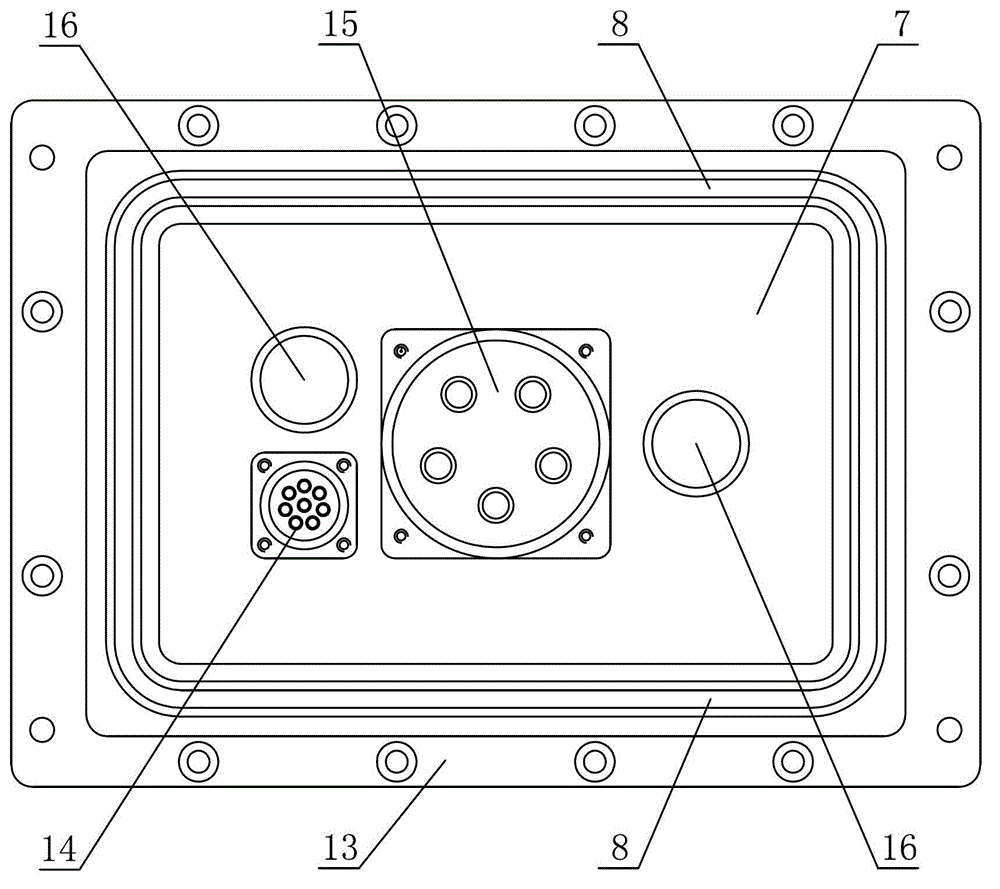
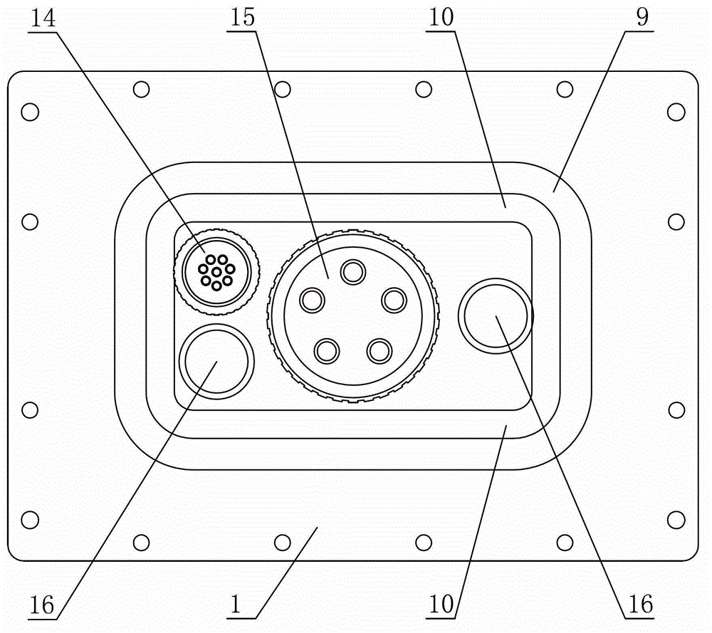
[0030] In such figure 1 , figure 2 , image 3 In the illustrated embodiment 1, a composite spring-type swimming socket includes a fixed seat 1 and a swimming seat 4 (see Figure 4 , The connector in the figure only shows the housing), the movable seat is provided with a connector and a connector guide 16, the connector includes a main connector 15 for transmitting large current and a secondary connector for transmitting control signals The plug-in 14, the plug-in guide is two asymmetrically arranged guide cylinders, the fixed seat is rectangular, the fixed seat is provided with a rectangular cavity 2 as a whole, and the bottom of the cavity is provided for passing through the connector and Insert the rectangular bottom hole 3 of the guide (see Figure 7 ), the movable seat 4 includes a rectangular movable plate 5 for fixing the above-mentioned connector and the insertion guide, the movable plate is arranged in a cavity on the fixed seat, and the thickness of the movable plate is...


PUM


Abstract

The invention discloses a compound spring type floating socket which comprises a fixed seat and a floating seat. Connectors and connecting guiding elements are arranged on the floating seat. A cavity is arranged in the fixed seat. A bottom hole which is used for the connectors and the connecting guiding elements to penetrate is formed in the bottom of the cavity. The floating seat comprises a floating plate which is used for fixing the connectors and the connecting guiding elements. The floating plate is arranged in the cavity of the fixed seat. The floating plate is movably connected with the fixed seat through a tension spring. An elastic piece is fixed on the upper surface of the floating plate. A receding hole is formed in the middle of the elastic piece. The periphery of the elastic piece extends outward and the edge of the outer side of the elastic piece is fixedly connected with the fixed seat. An elastic extensible structure which surrounds the floating plate is formed on the elastic piece close to the periphery of the floating plate. The compound spring type floating socket has the advantages of being capable of achieving multi-direction movement, good in vibration resistant effect, flexible in floating and high in operational reliability and practical value.

Description

Technical field [0001] The invention relates to a connector, in particular to a composite spring type swimming socket capable of realizing three-dimensional swimming. Background technique [0002] The prior art swimming (or floating) connector seat can only move on a plane perpendicular to the insertion direction (horizontal), but has no swimming function in the insertion direction (longitudinal) of the connector. Therefore, The main function of this kind of floating connector is to facilitate blind mating. At the same time, it also has anti-vibration function on the horizontal plane perpendicular to the mating direction. However, the vibration of the connector caused by the equipment or environment in actual use is not limited to the horizontal plane. Vibration also exists in the plugging direction of the connector, and the vibration in the plugging direction is most likely to loosen the plug connection between the connectors and cause the connection to be disconnected. Therefor...

Claims


Application Information

Patent Timeline
Patent Type & Authority Patents(China)
IPC IPC(8): H01R13/631H01R13/52
Inventor 王吉国
Owner ZHEJIANG ZHONGHANG ELECTRONICS
Why Eureka
Try Eureka