
A-shaped safety ladder

A safety ladder, A-shaped technology, applied in the direction of ladders, buildings, building structures, etc., can solve the problems of construction personnel falling, injury, construction personnel electric shock, etc., to achieve the effect of strengthening strength and stability, and maintaining body balance

Active Publication Date: 2013-05-01
YAU LEE CONSTR
View PDF7 Cites 1 Cited by
  • Summary
  • Abstract
  • Description
  • Claims
  • Application Information

AI Technical Summary

Problems solved by technology

[0003] The climbing work on the construction site often needs to change the construction position with the progress of the construction. In order not to delay the work progress, or feel that it is troublesome to climb up and down and move the ladder, some construction workers directly ride on the top of the ladder and step on the people. On the crossbars on both sides of the ladder, move the ladder directly with your feet, and use the inertia of the body to move the ladder left and right or even forward and backward to reach a new construction position. Sometimes the construction workers even step on the top of the ladder with both feet Although it can speed up the work progress, the whole process has to rely on the feet to hold the ladder, and the construction workers will fall from the ladder and be injured if they are not careful.
On the other hand, many power supply facilities on the construction site are temporarily built, and the wires are often exposed to the construction ground. When the ladder made of metal materials touches the damaged wires, it will cause the construction workers to get an electric shock.

Method used


Image

  • A-shaped safety ladder

Examples


Embodiment Construction

[0012] Embodiments of the present invention will be further described in detail below in conjunction with the accompanying drawings.

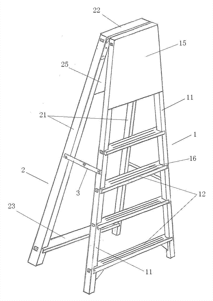
[0013] Such as figure 1 As shown, the safety A-shaped ladder of the present invention is mainly composed of a front ladder body 1 and a rear side ladder body 2. 3 to form an A-shaped structure.

[0014] The left and right sides of the front side ladder body 1 are respectively provided with a front support column 11, and a plurality of cross pedals 12 are fixed horizontally between the front support columns 11 on the two sides, and the distance between adjacent cross pedals 12 is about 305 mm, this distance can be properly adjusted according to the height of the ladder. Horizontal pedal 12 is designed as flat plate, and its width is 70-80 millimeters, and thickness is 15-25 millimeters, and the contact surface when stepping on can be increased, improves safety performance, and width is 75 millimeters among the present embodiment, and thickness...


PUM


Abstract

The invention relates to an A-shaped safety ladder comprising a front side ladder body (1) and a back side ladder body (2) hinged on the top. The front side ladder body (1) comprises front supporting columns (11) arranged on left and right sides and a plurality of horizontal pedals (12) horizontally bridged between the front supporting columns (11) arranged on the two sides. The back side ladder body (2) comprises back supporting columns (21) arranged on left and right sides and an upper connection rod (22) and a lower connection rod (23) respectively connecting the tops and bottoms of the back supporting columns (21) arranged on the two sides. No horizontal pedal is arranged between the upper and lower connection rods. A front closure plate (15) and a back closure plate (25) stopping a user from climbing to the ladder top are respectively fixedly arranged on the upper parts of the front side ladder body and the back side ladder body. A construction worker can lean his body against the closure plates, such that body balance can be maintained during climbing operations, and ladder body strength and stability can be enhanced. With the A-shaped safety ladder, a user is prevented from crossing both sides of the ladder, and is prevented from climbing to the ladder top, such that accidents are prevented. The ladder body adopts an insulating material which prevents electric shock, such that the ladder is safer to use.

Description

technical field [0001] The invention and a device for climbing heights, in particular, an insulating A-shaped ladder used on construction sites. The device of the invention is applicable to construction sites such as construction, decoration, maintenance, etc. The use of the device of the invention can greatly improve the safety of construction sites sex. Background technique [0002] Auxiliary climbing tools are often used on construction sites, decoration and maintenance sites, and administrative regulations in some places also stipulate that workbenches are required when working more than 2 meters above the ground. Auxiliary climbing operation tools commonly used on construction sites generally use ladders at present. The invention patent with the patent number of 200520063300.0 discloses a self-locking safety miter ladder, which is composed of two straight ladder bodies connected by connectors. The parts are formed by connecting the left coupling pair and the right cou...

Claims


Application Information

Patent Timeline
Patent Type & Authority Applications(China)
IPC IPC(8): E06C1/383E06C7/08
Inventor 黄天祥黄慧敏
Owner YAU LEE CONSTR
Learn More