Method and device for the dry forming of a fibre web

A fiber web and fiber technology is applied in the field of devices implementing the method to achieve the effect of suppressing the reverse effect and avoiding the turbulent effect

Inactive Publication Date: 2013-05-01
OERLIKON TEXTILE GMBH & CO KG
View PDF11 Cites 0 Cited by
  • Summary
  • Abstract
  • Description
  • Claims
  • Application Information

AI Technical Summary

Problems solved by technology

Although the inflow of secondary air from the environment can thus be avoided to a large extent, there is a disadvantage that the fiber layer is compacted on the surface of the deposit belt directly on the outlet side by the sealing roller arranged there.

Method used


Image

  • Method and device for the dry forming of a fibre web
  • Method and device for the dry forming of a fibre web

Examples


Embodiment Construction

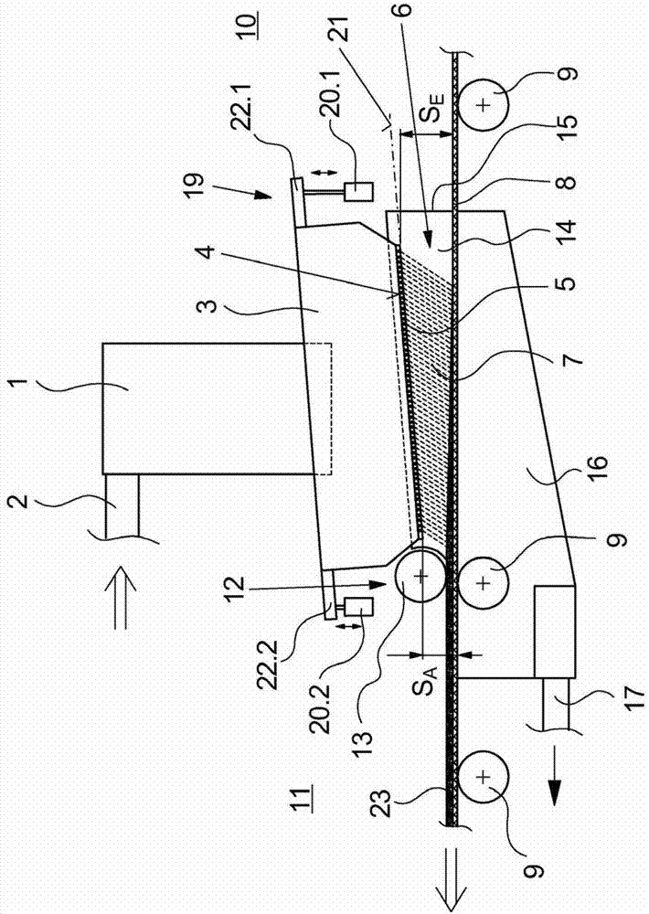
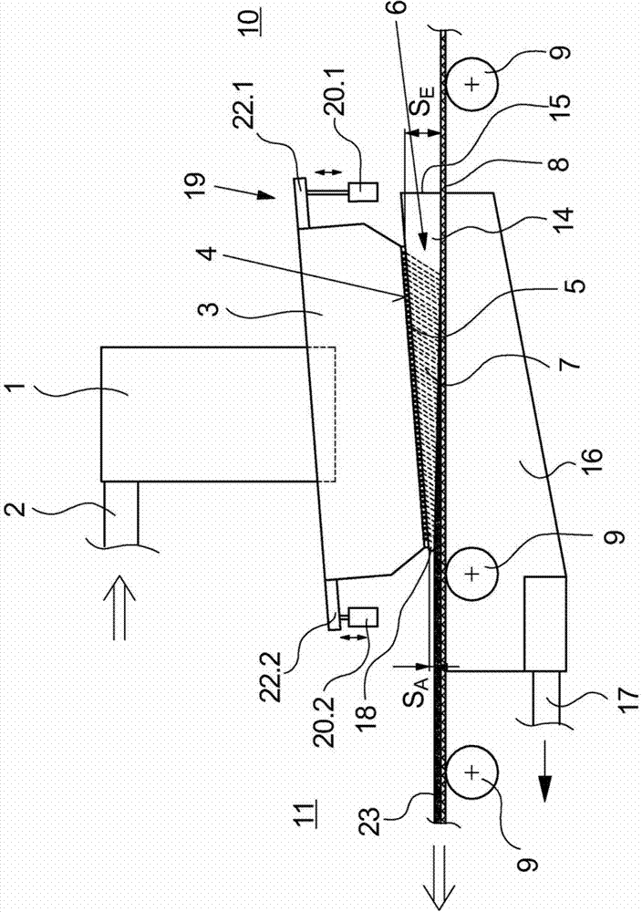
[0030] exist figure 1 A first exemplary embodiment of the device according to the invention for carrying out the method according to the invention is schematically shown in . This exemplary embodiment shows a mixing chamber 1 which is connected via a fiber inlet 2 to a fiber feed (not shown here). The fiber inlet 2 may comprise one or more connections in order to introduce one or more fibers or fiber mixtures into the mixing chamber 1 with an air flow. The mixing chamber 1 is connected on the bottom side to the forming head 3 . The forming head 3 has a plurality of means, not shown in detail here, for distributing the fibers or the fiber mixture and for discharging the fibers or the fiber mixture uniformly as a fiber stream via forming outlets 4 formed on the bottom surface. The shaping outlet 4 preferably has a plurality of sieve plates 5 . The distribution within the forming head is preferably achieved here by means of a plurality of driven blades (as is known, for exampl...


PUM


Abstract

The invention relates to a method and a device for the dry forming of a fibre web, in which a multiplicity of fibres or fibre mixtures are fed to a forming head by means of an air flow. The forming head produces a fibre stream which is introduced into a clearance of a forming zone between the forming head and a laydown belt. The fibres are received on the laydown belt and are shaped to form a fibre layer which is conveyed continuously out of the forming zone via the laydown belt. In order to obtain as uniform a construction of the fibre layer as possible during the laying down of the fibres, according to the invention the fibres of the fibre stream run through the clearance within the forming zone with free sections of different lengths. To this end, the forming head and the laydown belt are held in a non-parallel arrangement, with the result that the clearance is formed by different spacings between the laydown belt and the forming outlet of the forming head.

Description

technical field [0001] The invention relates to a method for dry forming of a fiber web according to the preamble of claim 1 and a device for carrying out the method according to the preamble of claim 7 . Background technique [0002] Such a method and such a device are known from WO 2004 / 106604 A1. [0003] For processing fibrous nonwovens, it is known to deposit the fibers in a fiber layer on a deposit belt by means of an air flow. The basis of this method, generally known in the technical field as air-laying, is the uniform distribution of fibers or fiber mixtures on the surface of the deposition belt by means of a forming head. The area of ​​the deposition belt covered by the forming head is generally referred to as the forming zone, in which the fibers meet on the deposition belt. Such a method and such a device are described, for example, in WO 2004 / 106604 A1. In this known method and known device, an air flow is used to transport a plurality of fibers or fiber mixt...

Claims


Application Information

Patent Timeline
IPC IPC(8): D04H1/732D04H1/736D01G25/00D04H1/74
CPCD01G25/00D04H1/736D04H1/005D04H1/732D04H1/74
Inventor O·施瓦茨I·梅尔曼R·索加德延森
Owner OERLIKON TEXTILE GMBH & CO KG
Why Eureka
Try Eureka