
Bidirectional axial flow pump

A two-way axial and axial flow technology, applied in the direction of axial flow pumps, pumps, pump components, etc., can solve problems such as large impact, impact on crop growth, and short delivery distance

Pending Publication Date: 2021-11-02
郑家龙
View PDF1 Cites 0 Cited by
  • Summary
  • Abstract
  • Description
  • Claims
  • Application Information

AI Technical Summary

Problems solved by technology

[0004] When the two-way axial flow pump in the above invention is in use, since the pump body relies on the pressure to pump the liquid, and then cooperates with the turbine blades to transport the liquid, this process has high requirements for the suction pressure of the axial flow pump, so the axial flow When the pump is in use, the length of the circulation pipe is often short, that is, the delivery distance is relatively short, and when the liquid is pumped and transported in the actual use process, the discharged liquid is mostly in a turbulent state. In ship applications and agricultural applications , turbulent flow has a greater impact on pumping and drainage, and at the same time, when the liquid is discharged, it will cause an impact on the hull, and at the same time affect the growth of crops in agricultural irrigation:

Method used


Image

  • Bidirectional axial flow pump
  • Bidirectional axial flow pump
  • Bidirectional axial flow pump

Examples


Embodiment Construction

[0034] The following will clearly and completely describe the technical solutions in the embodiments of the present invention with reference to the accompanying drawings in the embodiments of the present invention. Obviously, the described embodiments are only some, not all, embodiments of the present invention. Based on the embodiments of the present invention, all other embodiments obtained by persons of ordinary skill in the art without making creative efforts belong to the protection scope of the present invention.

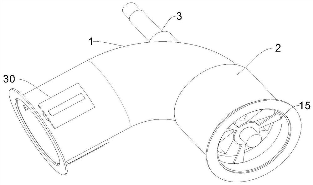
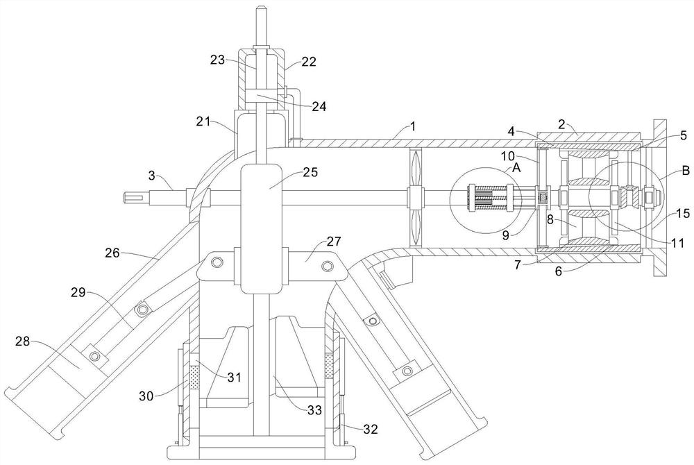
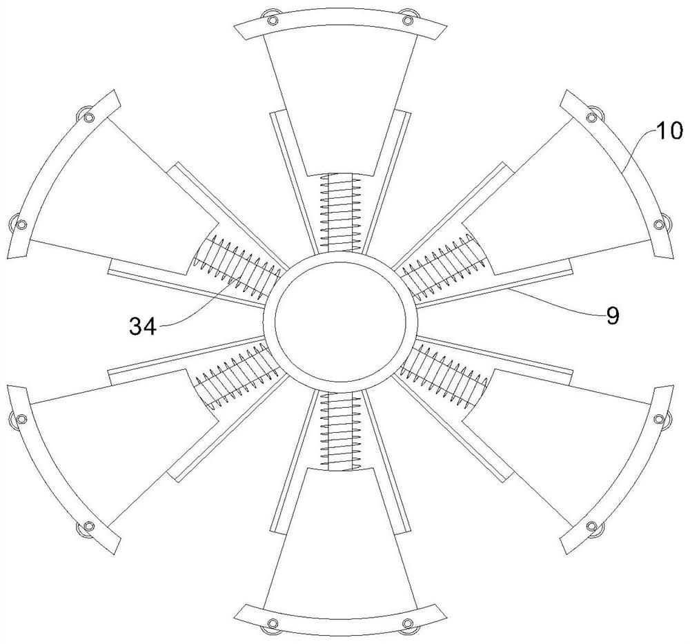
[0035] see Figure 1 to Figure 7 , the present invention provides a technical solution:

[0036] A bidirectional axial flow pump such as Figure 1 to Figure 7 As shown, the axial flow tube 1 is included, and the axial flow tube 1 is connected with the drive shaft 3 through rotation, the side wall of the drive shaft 3 is fixedly connected with the axial flow fan blade, and the right end surface of the axial flow tube 1 is fixedly connected with the support fra...


PUM


Abstract

The invention discloses a bidirectional axial flow pump. The bidirectional axial flow pump comprises an axial flow pipe, a driving shaft is rotationally connected in the axial flow pipe in a penetrating manner, axial flow fan blades are fixedly connected to the side wall of the driving shaft, a supporting frame is fixedly connected to the right side end face of the axial flow pipe, the driving shaft is rotationally connected with the supporting frame in a penetrating manner, an outer fixed ring is fixedly connected to the side wall of the axial flow pipe, a mounting groove is formed in the inner side wall of the outer fixed ring, and a first flow stabilizing mechanism used for carrying out flow stabilizing treatment on water discharged out of the axial flow pipe is arranged in the mounting groove. By arranging the first flow stabilizing mechanism and a second flow stabilizing mechanism, the first flow stabilizing mechanism is used for carrying out the speed reduction process on the rotating state of discharged liquid, spiral turbulent flow of the liquid is adjusted, meanwhile, the second flow stabilizing mechanism and vortex fan blades rotate in the opposite directions, the liquid is in a flow stabilizing state when being discharged out of the pipeline, and the situation that crops and steamships are affected by turbulent flow in the water suction process due to direct discharge of liquid in the turbulent flow state is avoided.

Description

technical field [0001] The invention relates to the technical field of axial flow pumps, in particular to a bidirectional axial flow pump. Background technique [0002] Axial flow pumps rely on the force generated by the blades of the rotating impeller on the liquid to transport the liquid along the axial direction. There are several types of vertical, horizontal, inclined and through-flow pumps. [0003] The existing patent (notification number: CN104989667A) is a two-way axial flow pump, which includes an impeller built into the pump body that rotates with the pump shaft. The pump body is in the shape of a curved tube, an inner shaft seat is provided in the cavity at one end, and an outer shaft seat coaxial with the inner shaft seat is provided on the outer wall of the curved section. The two ends of the pump shaft are respectively supported and rotated by the inner shaft seat and the outer shaft seat, and the extended end of the pump shaft is connected to the output shaf...

Claims


Application Information

Patent Timeline
IPC IPC(8): F04D29/66F04D29/00F04D3/00
CPCF04D29/669F04D29/007F04D3/00
Inventor 郑家龙林胜杰
Owner 郑家龙
Learn More