
Control device for continuously variable transmission for use in vehicles

A technology of continuously variable transmission and control device, which is applied in the direction of transmission, transmission control, components with teeth, etc., and can solve problems such as belt slippage

Active Publication Date: 2015-02-25
TOYOTA JIDOSHA KK
View PDF7 Cites 0 Cited by
  • Summary
  • Abstract
  • Description
  • Claims
  • Application Information

AI Technical Summary

Problems solved by technology

During a downshift, since the shift differential thrust on the primary side becomes a negative value, the set target main thrust tends to be lower than the minimum slip critical thrust (required main thrust) required to prevent the primary pulley from slipping. , so that belt slippage may occur
In addition, during an upshift, since the shift differential thrust on the main side becomes a positive value, the set target main thrust is unlikely to be lower than the required main thrust, but it may be lower than the required main thrust due to the balance thrust on the main side, etc. belt slip

Method used


Image

  • Control device for continuously variable transmission for use in vehicles
  • Control device for continuously variable transmission for use in vehicles
  • Control device for continuously variable transmission for use in vehicles

Examples


Embodiment

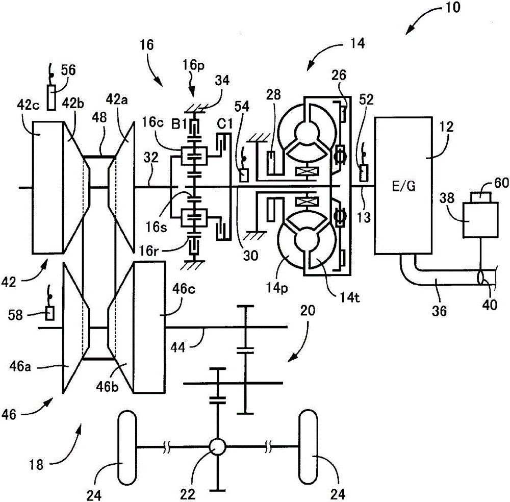
[0035] figure 1 It is a figure explaining the schematic structure of the power transmission path from the engine 12 to the drive wheel 24 which comprises the vehicle 10 to which this invention is applied. exist figure 1 Among them, for example, the power generated by the engine 12 used as a driving force source for traveling passes sequentially through a torque converter 14 as a fluid transmission device, a forward and reverse switching device 16, and a belt-type continuously variable transmission as a vehicle continuously variable transmission ( Hereinafter, a continuously variable transmission (CVT) 18 , a reduction gear unit 20 , a differential gear unit 22 , and the like transmit transmission to left and right drive wheels 24 .

[0036] The torque converter 14 has a pump impeller 14p connected to the crankshaft 13 of the engine 12, and a turbine 14t connected to the forward / reverse switching device 16 via a turbine shaft 30 corresponding to an output side member of the to...


PUM


Abstract

A control device of a continuously variable transmission for a vehicle having a pair of variable pulleys with variable effective diameters of an input-side variable pulley and an output-side variable pulley and a transmission belt wound around between the pair of the variable pulleys, the continuously variable transmission respectively controlling an input-side thrust force in the input-side variable pulley and an output-side thrust force in the output-side variable pulley to set an actual gear ratio to a target gear ratio while preventing a slip of the transmission belt, the continuously variable transmission includes: a hydraulic control circuit capable of accurately controlling one of the input-side variable pulley and the output-side variable pulley in terms of thrust force as compared to the other, in the case that a target thrust force on the one side for assuring belt slip prevention of the both pulleys on the one side is set, based on a target thrust force on the one side, a target thrust force on the other side for achieving a target gear ratio on the other side being set, and a larger one being selected as the target thrust force on the one side out of a limit thrust force to a slip on the one side required for belt slip prevention on the one side, and a thrust force on the one side required for achieving a target gear ratio on the one side calculated based on a limit thrust force to a slip on the other side required for belt slip prevention on the other side.

Description

technical field [0001] The present invention relates to a control device for a continuously variable transmission for a vehicle (belt type continuously variable transmission) that prevents belt slip and realizes a target gear ratio by separately controlling input side thrust and output side thrust. Background technique [0002] A control device of a continuously variable transmission for vehicles (hereinafter, referred to as a continuously variable transmission) having an input side variable pulley (primary pulley, primary sheave) and an output side variable pulley is well known. A pair of variable pulleys (slave pulley: secondary pulley, slave pulley: secondary sheave) whose effective diameter is variable, and a transmission belt wound between the pair of variable pulleys are controlled separately The input side thrust of the main pulley (master thrust) and the output side thrust of the slave pulley (slave thrust) prevent the belt from slipping and make the actual gear rati...

Claims


Application Information

Patent Timeline
Patent Type & Authority Patents(China)
IPC IPC(8): F16H61/02
CPCF16H61/66259F16H61/02F16H61/66272F16H9/125
Inventor 服部邦雄丰田晋哉绫部笃志
Owner TOYOTA JIDOSHA KK
Learn More