Positioning device with limiting function

A positioning device and position limiting technology, applied in the direction of positioning device, clamping, support, etc., can solve the problems of clamping that cannot be mass-produced, waste of materials, waste of processing time, etc.

Inactive Publication Date: 2013-05-08
CHONGQING MING SHIELD ELECTROMAGNETIC VALVE
View PDF0 Cites 7 Cited by
  • Summary
  • Abstract
  • Description
  • Claims
  • Application Information

AI Technical Summary

Problems solved by technology

[0002] During mechanical processing, the shape and size of the processed parts are different. Usually, the positioning device is made separately for the processed parts. However, it will be wasteful to use this method when facing the processed parts with similar appearance and similar size. Material, there is no need to do this. Later, a fixture was improved and a spring was installe

Method used


Image

  • Positioning device with limiting function

Examples


Embodiment Construction

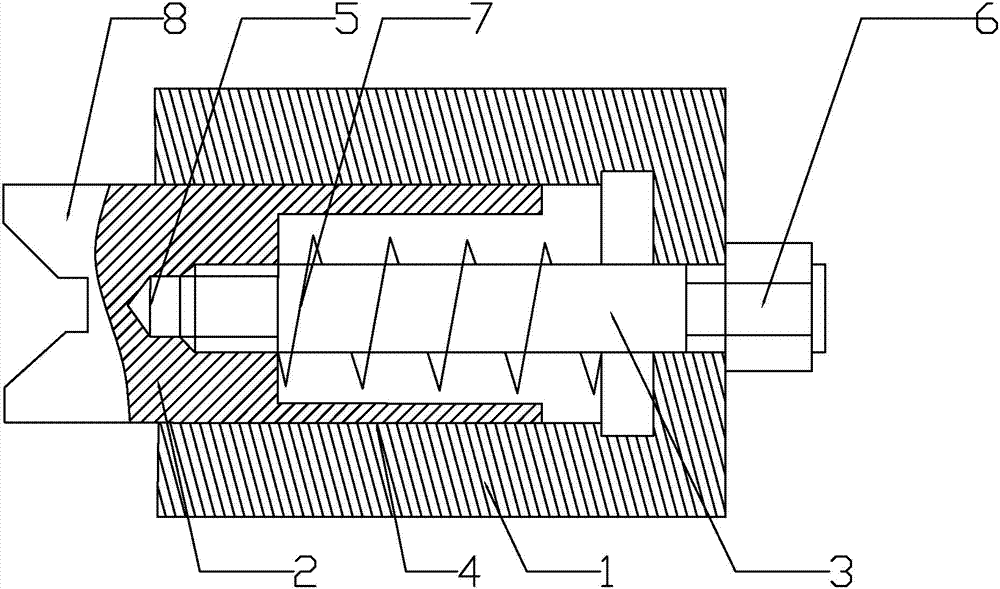
[0009] As shown in Figure 1, the present invention is a kind of limitable positioning device, comprises base plate 1, splint 2, screw rod 3, and the front end of described base plate 1 is provided with V-shaped block 8, and rear end is provided with threaded hole 5, so The rear end of the splint 2 is embedded in the chute 4 provided on the base plate 1, one end of the screw 3 passes through the base plate 1 and is connected and fixed with the threaded hole 5 at the rear end of the splint 2, and the other end of the screw 3 is positioned on the base plate 1 by a nut 6 .

[0010] A spring 7 is sleeved between the bottom plate 1 and the splint 2 on the screw rod 3 , so as to prevent the splint 2 from being stuck in the chute 4 of the bottom plate 1 .

[0011] Put in the workpiece, in order to clamp the workpiece, the splint 2 is displaced, the length of the screw 3 outside the bottom plate 1 changes, and then the screw 3 exposed outside the bottom plate and the bottom plate 1 are...


PUM


Abstract

The invention discloses a positioning device with a limiting function. The positioning device comprises a bottom plate, a clamping plate and a screw; the front end of the bottom plate is provided with a V-shaped block, and the rear end of the bottom plate is provided with a threaded hole; the rear end of the clamping plate is embedded into a sliding chute formed on the bottom plate; one end of the screw penetrates through the bottom plate and is fixedly connected with the threaded hole at the rear end of the clamping plate, and the other end of the screw is positioned on the bottom plate through a nut; the defects that a clamp has a single purpose, because a clamping plate can only clamp a workpiece with one size in the prior art can be overcome; and the improved positioning device is provided, workpieces with different sizes can be processed, and the manufacturing cost of the clamp is saved.

Description

technical field [0001] The invention belongs to a machining positioning fixture, in particular to a position-limiting positioning device. Background technique [0002] During mechanical processing, the shape and size of the processed parts are different. Usually, the positioning device is made separately for the processed parts. However, it will be wasteful to use this method when facing the processed parts with similar appearance and similar size. Material, there is no need to do this. Later, a fixture was improved, and a spring was installed inside. Although the elastic force of the spring was used to increase the size of the workpiece clamped by the positioning device, a new problem appeared. Finally, the fixture is reset, and the next time the same type of workpiece is loaded, it needs to be clamped again, resulting in a waste of processing time, and it cannot be clamped in large quantities. Contents of the invention [0003] The technical problem to be solved by the ...

Claims


Application Information

Patent Timeline
IPC IPC(8): B23Q3/00
Inventor 姜静慧
Owner CHONGQING MING SHIELD ELECTROMAGNETIC VALVE
Why Eureka
Try Eureka