Rocket launcher for ship

A launcher and rocket technology, applied in the field of launchers, can solve the problems of high height of the launcher, overturning of the support mechanism, difficulty in loading ammunition, etc., and achieve the effects of ensuring launch accuracy, easy adjustment, and easy loading.

Pending Publication Date: 2020-04-24
新余国科特种装备有限公司
View PDF0 Cites 3 Cited by
  • Summary
  • Abstract
  • Description
  • Claims
  • Application Information

AI Technical Summary

Problems solved by technology

[0002] At present, meteorological rockets have become the main tool for artificial weather modification operations. Rocket launchers, as rocket launch platforms, play an important role in shadow operations; existing launchers are launched manually, manually calibrated, and on-site Cables, the operating procedures are cumbersome and complicated, and as the support angle of the launcher increases, the support mechanism is prone to overturning under the heavy pressure of the launcher, and the overall height of the launcher is high, making it difficult to load

Method used


Image

  • Rocket launcher for ship
  • Rocket launcher for ship
  • Rocket launcher for ship

Examples


Embodiment 1

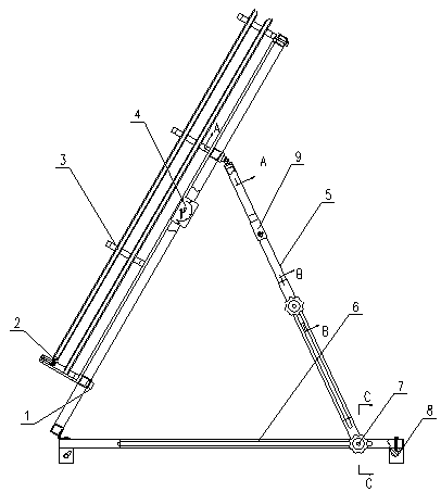
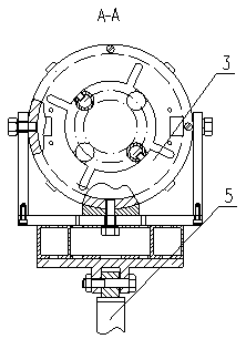
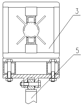
[0028] see Figure 1-7 , a rocket launcher for ships of the present invention, comprising a socket 1, a bullet stopper 2, an orienter 3, an angle meter 4, a telescopic rod 5, a chassis 6, a fastening bolt 7 and a magnetic base 8, and the socket 1 is an aviation Six-pin socket, socket 1 is used for electrical connection with the launch controller, and socket 1 is set on the left side of the bottom of the orientator 3 used to control the initial launch direction of the rocket. The bullet stopper 2 blocks the tail of the rocket, and the middle side of the bottom of the directional device 3 is equipped with an angle meter 4 indicating the elevation angle of the directional device 3. The right side of the bottom of the directional device 3 is connected to the telescopic rod 5 in rotation and fixed with it by bolts, and stretches The upper rod and the lower rod of the rod 5 are locked and matched with each other through the fastening bolt 7. The bottom of the telescopic rod 5 is loc...

Embodiment 2

[0030] see Figure 8 , a rocket launcher for ships of the present invention, the fine-tuning structure 9 includes a lower sleeve 91, a hand wheel 92, a first bevel gear 93, a second bevel gear 94, a pole 95, a screw rod 96, an internal thread sleeve 97, Last sleeve 98 and spacer 99, the bottom of lower sleeve 91 and the top of upper sleeve 98 separate the upper rod of telescopic rod 5 into two sections and fix it therewith, thereby changing the distance between the two sections of telescopic rod 5. The distance position, the hand wheel 92 runs through the bottom of the right part of the lower sleeve 91 and is connected to it in rotation. The inner side of the hand wheel 92 is welded to the first bevel gear 93, and the first bevel gear 93 is driven by the hand wheel 92 to rotate. The first bevel gear The bottom of 93 meshes with the second bevel gear 94, and the second bevel gear 94 is rotationally connected with the lower sleeve 91. The middle side of the top of the second bev...


PUM


Abstract

The invention discloses a rocket launcher for a ship. The rocket launcher comprises a socket, a bomb blocking device, an orientator, an angle gauge, telescopic rods, a chassis, a fastening bolt and amagnetic seat, and the fixed chassis is arranged and is fixed on the ship through the magnetic seat, so that the possibility that the launcher turns over is eliminated; the telescopic rods are arranged on the inner sides of the orientator and the chassis, the bottoms of the telescopic rods can transversely slide on the chassis to change the supporting position of the orientator, and the telescopicrods can stretch out and draw back, so that the height and the angle of the orientator are convenient to adjust, and bullet loading is convenient.

Description

technical field [0001] The invention relates to the related field of launchers, in particular to a ship rocket launcher. Background technique [0002] At present, meteorological rockets have become the main tool for artificial weather modification operations. Rocket launchers, as rocket launch platforms, play an important role in shadow operations; existing launchers are launched manually, manually calibrated, and on-site The cables and operating procedures are cumbersome and complicated, and as the support angle of the launcher increases, the support mechanism is prone to overturning under the heavy pressure of the bomber, and the overall height of the launcher is high, making it difficult to load. Contents of the invention [0003] Therefore, in order to solve the above disadvantages, the present invention provides a ship rocket launcher. [0004] The present invention is achieved in that a kind of ship rocket launcher is constructed, and the device includes a socket, a...

Claims


Application Information

Patent Timeline
Patent Type & Authority Applications(China)
IPC IPC(8): B63G1/00F41F3/04
CPCB63G1/00F41F3/04
Inventor 邹春根朱科平王璞龚毅曾闰平顾春涛黄欢张亮亮常江邵文政
Owner 新余国科特种装备有限公司
Why Eureka
Try Eureka